Display
On the Display tab of the Drillhole Imaging form, choose a Cylinder or a Billboard display mode.
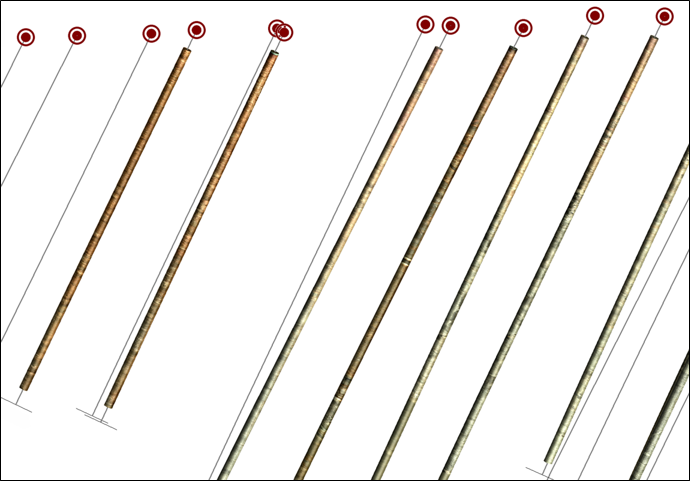
Cylinder
Select this option to show imaging cylindrically down the hole.
Image Orientation
Optionally, choose a method of image orientation.
Each image is oriented so that its left-hand edge is aligned to north (0° azimuth) in the working coordinate system and its right-hand edge is 360° azimuth. The image is scaled to fit the diameter of the cylinder used to create a solid trace for each hole.
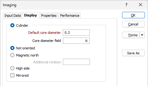
When an image is oriented to Magnetic North, the left-hand edge of the unrolled image corresponds to a magnetic azimuth of zero. Use the additional rotation option to align the images to a different north point.
In High Side mode, a line along the top of the core cylinder corresponds to an azimuth of zero.
You can use the Mirrored option to adjust images acquired from inside a drillhole (a "wall view") so that they resemble a stick of core viewed from outside (a "Core view"). You must understand your data here, as mirroring is often applied in the imaging software before exporting to the application. Mirroring is not required for images acquired directly from drill core.
Cylinder Diameter
To specify the diameter of the cylinders:
Enter the diameter (in millimetres) for the holes along the row. Hole diameter is a fundamental factor in blast geometry since it affects the results that can be achieved from blasting.
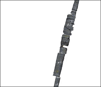
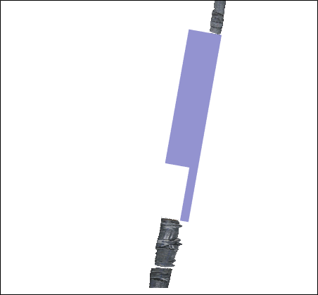
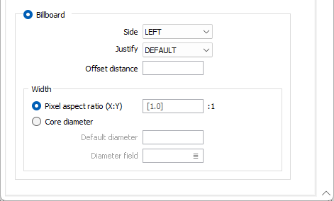
Billboard
Select this option to show half-cut core images as a billboard along the trace. The billboard is a flat view of the imaging data which is oriented to match the current view direction.
Side
The billboard can be displayed to the LEFT or to the RIGHT of the drillhole trace.
Justify
Specify how the images will be justified by selecting a (DEFAULT or CENTRE) option from the drop-down list.
If you select DEFAULT, left justification is applied if the billboard is on the RIGHT side of the trace, right justification is applied if the billboard is on the LEFT side of the trace.
Select CENTRE to centre the billboard on the trace.
Offset distance
Define the distance the billboard will be offset from the trace (in grid units). The default is 1. Both positive and negative values are acceptable.
Billboard Width
Choose how the width of the billboard will be calculated:
Pixel aspect ratio (X:Y)
Select this option to calculate the billboard width based on the depth of each interval and the width and height of each image. The default pixel aspect ratio is 1:1.
Core Diameter
Select this option to calculate the billboard width based on the diameter of the core.
Enter the diameter (in millimetres) for the holes along the row. Hole diameter is a fundamental factor in blast geometry since it affects the results that can be achieved from blasting.
Forms
Click the Forms button to select and open a saved form set, or if a form set has been loaded, save the current form set.
By design, the Forms button is not available for loaded Vizex layers (i.e. when opening the form set properties of a layer in the Vizex Layer Display pane). In Vizex, the Forms button is only available for new forms opened via the Home tab or the Vizex tab, in the Layer group (or by double-clicking on a form type node in the Vizex Layer Types pane).
Save and Save As
Click the Save button to save the changes you have made to the form set. Click Save As to save your changes as a new form set. Save As will default to the first available form set number.
Reset
Click Reset to clear the form of all values and reset the form to its default state.
Reset Tab
For tabbed forms, select Reset Tab to clear the active tab of all values and reset the tab to its default state - without making any changes to other tabs in the dialog.
Undo and Redo
Click Undo (CTRL + Z) to undo recent changes in the form. After an Undo, click Redo (CTRL + Y) to restore the last change that was undone.
Collapse
Collapse (roll-up) the form to preview a chart, or preview the results of an operation in Vizex, or obtain input values from Vizex, the Property Window, the File Editor, or the Plot Editor.