Imaging
Imaging is ideal for verifying a geological interpretation by providing direct access to the images within the Vizex window.
![]()
Downhole images may be obtained from any image source, such as 360° core scanners and downhole optical/acoustic imaging systems. Any source that maintains a constant scale, can be depth referenced, and shows the full core cylinder is suitable.
Images acquired using downhole methods (which capture the inside of the drillhole) must be mirrored so that they resemble the “core” as viewed from the outside.
Each drillhole may be imaged using any number of separate images. Downhole surveys typically capture one image per hole, whereas core scanners may acquire individual images on a per-interval basis. The application requires an interval file containing the Hole ID, From/To values, and File Name for each image. Like any Micromine interval file, the images do not need to be contiguous or cover the entire length of the hole.
Input Data
Database
Trace coordinates are generated automatically when you create a drillhole database. The database contains the collar and (optionally) the survey data needed to generate the trace.
Double-click (F3) to select
Select the Filter check box if you want to apply a filter to the database. Enter a filter number in the adjacent response. Double click (F3) to see a list of existing filters. Right click (F4) to open the dialog box where you can create a new filter.
Interval file
Double-click (or click on the Select icon) to select the name of the Interval file that contains the image data you want to drape along the holes, with each image referenced to a Hole ID and a From/To interval.
Select the Filter check box if you want to apply a filter to the file. Enter a filter number in the adjacent response. Double click (F3) to see a list of existing filters. Right click (F4) to open the dialog box where you can create a new filter.
Image field
A field in the Interval file must contain the names of the image files that will be draped along the trace. Double-click (or click on the List icon) to select the field.
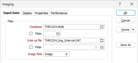
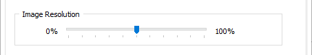
Image Resolution
Core images are often of a very high resolution. To speed up loading times, use the slider control to set the display resolution of those images on-the-fly. The default display resolution is 50% of the original resolution of the image. Note that the underlying image file is not changed.
Transparent Colour
Double-click on the Colour icon to set a colour as transparent. This makes it possible, for example, to set as transparent the black (or white) border that surrounds a scanned map or an aerial photo.
This transparency is honoured in the Plot Editor when you plot an image. Note however that compressed image formats (like JPEG 2000, ECW, or MrSID) may be prone to “artifacting” (unwanted pixelisation or strange halos in areas of solid colour).
Tolerance
You can use the Tolerance setting to control the extent of the colour transparency.
The best tolerance depends on the image. A smaller tolerance may be suitable if the image is of high quality and is uncompressed, or compressed using a lossless method. A larger tolerance is needed for lossy compression formats like ECW, SID, JPG, or JP2 because the compression process always degrades areas that should contain the same pixel brightness values.
Powers of two are suitable values for an initial tolerance. Tolerances of 4 or 8 are typically used for high quality uncompressed images, whereas tolerances of 16 or 32 may be necessary for compressed images. Once an initial tolerance is found it may be refined by choosing an integer value near the chosen power of two. It may be impossible to find a suitable tolerance for highly compressed low-quality images, since the noise in these images often exceeds the range of the actual image data. Choosing too large a tolerance in this situation will erode actual image data without fully removing the surrounding to-be-transparent area.
![]()
Forms
Click the Forms button to select and open a saved form set, or if a form set has been loaded, save the current form set.
By design, the Forms button is not available for loaded Vizex layers (i.e. when opening the form set properties of a layer in the Vizex Layer Display pane). In Vizex, the Forms button is only available for new forms opened via the Home tab or the Vizex tab, in the Layer group (or by double-clicking on a form type node in the Vizex Layer Types pane).
Save and Save As
Click the Save button to save the changes you have made to the form set. Click Save As to save your changes as a new form set. Save As will default to the first available form set number.
Reset
Click Reset to clear the form of all values and reset the form to its default state.
Reset Tab
For tabbed forms, select Reset Tab to clear the active tab of all values and reset the tab to its default state - without making any changes to other tabs in the dialog.
Undo and Redo
Click Undo (CTRL + Z) to undo recent changes in the form. After an Undo, click Redo (CTRL + Y) to restore the last change that was undone.
Collapse
Collapse (roll-up) the form to preview a chart, or preview the results of an operation in Vizex, or obtain input values from Vizex, the Property Window, the File Editor, or the Plot Editor.