Seismic (SEG-Y)
The SEG-Y-file format is one of several standards developed by the Society of Exploration Geophysicists for storing geophysical and Seismic Data.
![]()
Seismic surveying is an essential tool for stratified deposits such as coal. Seismic data is easily combined with drillholes in the application, providing another layer of information and improving the quality of the resulting models.
Vizex supports the 2D and 3D SEG-Y formats used by geophysicists.
-
The 2D Seismic (SEG-Y) layer supports common processing options like manual adjustments, automatic gain control and vertical depth/time adjustments. Display options such as trace thickness, colour and fill make it easy to produce a visually informative display.
-
The 3D Volume layer supports processing options for in-line and cross-line sampling. Colour, 3D Shaded and 2D Slice draw styles, and layer transparency, can all be applied to the model. An option to generate isosurfaces around discontinuities detected during seismic interpretation, is also provided.
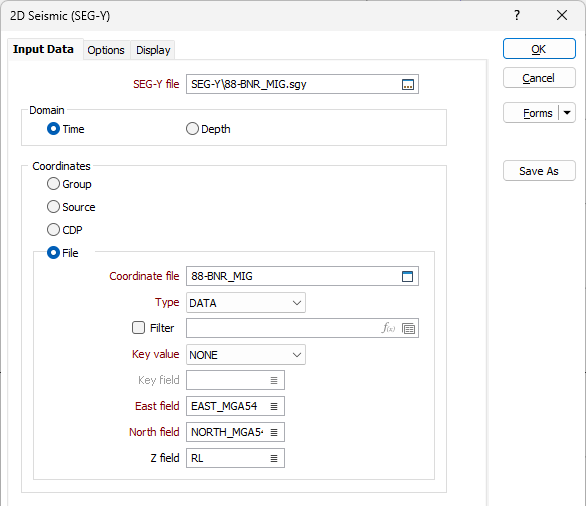
Input Data
SEG-Y File
Double-click (or click on the Select icon) in the File box to select an Input (*.sgy, *.segy) file. You can right-click in the File box to display basic information about the file (the revision of SEG-Y, the sample count, the sample interval from the Binary Header, and the text in the basic Text Header).
Domain
Chose whether the domain of the data is Time or Depth.
Coordinates
Select an option that will be used to obtain the XY coordinates of each trace. There are four options:
- Group: (bytes x=81-84, y=85-88)
- Source: (bytes x=73-76, y=77-80)
- CDP: (bytes x=181-184, y=185-188) Revision 1.0 only
The values from these bytes will be modified by the coordinate scalar at bytes 71-72.
- File: Select a file containing the X, Y, and optionally Z coordinates for the Traces.
Additionally, this file can contain a Key Field to link the coordinates to a specific trace. The Key can be the Source Point (bytes 17-20), Trace in Line (bytes 1-4), Trace in File (bytes 5-8) where the value in the file should match the value in the trace header. If the Key value is None then trace 1 will have the coordinates defined in row 1 and so on...
Select a file type and then double-click (or click on the Select icon) in the Coordinate file box to select the file that contains the trace coordinates. Specify the required (Key, East, North) fields in the file.
Detect elevation
The Z coordinate can either be obtained from the SEG-Y file, as defined in the form, or be obtained from the Coordinate file described above.
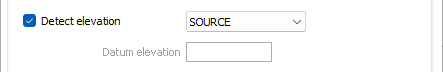
If the Detect elevation check box is selected, then the Z coordinate is read from the SEG-Y file:
| GROUP | (bytes 41-44) |
| GROUP (DATUM) | (bytes 53-56) |
| SOURCE |
(bytes 45-48) |
| SOURCE (DATUM) | (bytes 57-60) |
The values from these bytes will be modified by the coordinate scalar at bytes 69-70.
Datum elevation
Otherwise, the elevation of every trace can be defined by the elevation value entered in the Datum elevation box.
Manual Adjustments
The following options allow you to override the scalar for X, Y and Z (elevation or depth) coordinates:
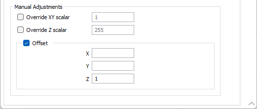
Override XY scalar
This will replace the scalar used when calculating the coordinates. Use the value entered here rather than the value in bytes 71-72. This scalar will be applied to the file coordinates as well.
Override Z scalar
This will replace the scalar used when calculating the elevation. Use the value entered here rather than the value in bytes 69-70.
The values in these scalars follow the same rules as in the SEG-Y. If positive, scalar is used as a multiplier; if negative, scalar is used as a divisor.
Offset
The coordinates calculated will all be offset by the values defined in the X, Y, and Z fields.
Forms
Click the Forms button to select and open a saved form set, or if a form set has been loaded, save the current form set.
By design, the Forms button is not available for loaded Vizex layers (i.e. when opening the form set properties of a layer in the Vizex Layer Display pane). In Vizex, the Forms button is only available for new forms opened via the Home tab or the Vizex tab, in the Layer group (or by double-clicking on a form type node in the Vizex Layer Types pane).
Save and Save As
Click the Save button to save the changes you have made to the form set. Click Save As to save your changes as a new form set. Save As will default to the first available form set number.
Reset
Click Reset to clear the form of all values and reset the form to its default state.
Reset Tab
For tabbed forms, select Reset Tab to clear the active tab of all values and reset the tab to its default state - without making any changes to other tabs in the dialog.
Undo and Redo
Click Undo (CTRL + Z) to undo recent changes in the form. After an Undo, click Redo (CTRL + Y) to restore the last change that was undone.
Collapse
Collapse (roll-up) the form to preview a chart, or preview the results of an operation in Vizex, or obtain input values from Vizex, the Property Window, the File Editor, or the Plot Editor.