GIS
![]()
You can also open a GIS layer from the Open Layer tool on the Vizex tab, in the Layer group.
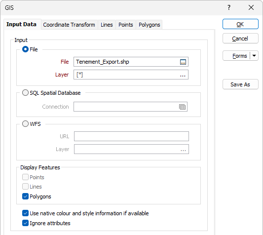
Input File
Double-click in the File input box to select the file to be loaded. File formats that can be loaded include Esri File Geodatabases (GDB), ArcGIS (.SHP) Shapefiles, Arc/Info Coverage files, SpatiaLite Database (.sqlite) files, GDAL CSV files, MapGIS files, Microstation® DGN files, and MapInfo® files in both TAB and MIF formats. Web Feature Service (WFS) connections via WFS:https URL are also supported. See GIS Web Feature Service (WFS) Connections.
For more detailed information, see Vector File Formats.
Layer
All layers will be loaded by default unless you click on the ellipsis button to choose a layer or layers to load. To select multiple layers, hold down the CTRL or the SHIFT key as you select layers with the mouse.
SQL Spatial Database
Select this option and click the Spatial Database Settings button to set the connection parameters of the spatial database you want to import data from.
WFS
GIS connections with Web Feature Service (WFS) via https URL are supported. Select this option to enter a URL and Layer for the connection.
URL
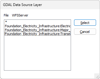
Enter the URL for the WFS in the format https:\\ For example, to use the Foundation Electricity Infrastructure data from Geoscience Australia Web Services, the URL would be:
https://services.ga.gov.au/gis/services/Foundation_Electricity_Infrastructure/MapServer/WFSServer
Layer
With the URL entered, you can click the ellipsis in the Layer field to select the GDAL Data Source Layer from the connected source:
Filter
The options in the Filter section of the form allow you to create an SQL WHERE statement to filter points data within a layer.
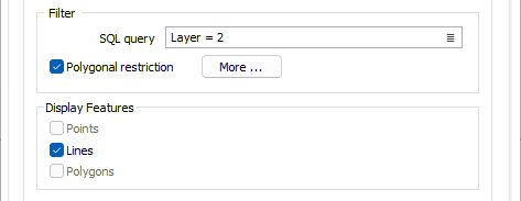
SQL query
The SQL query filter provides a list of attributes in the GIS layer which can be added to the SQL statement you create in the field. Click the list button to open the list:
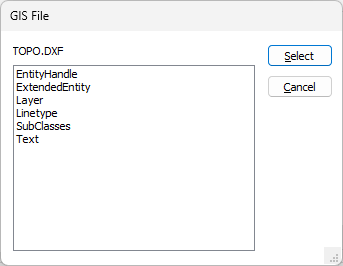
Using the attributes in the list, you can populate the SQL query for the filter. If the SQL statement submitted is invalid, an error will be displayed.
Note: In some cases, the filter may not be applied if you have added an attribute to your statement that is not shared among all feature types (i.e. points, lines, polygons etc.) and the statement will be treated as invalid.
If the Polygonal Restriction option is selected, you can define a polygon to be used to restrict the GIS data displayed:
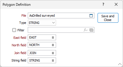
The polygon you define in the dialog can be used to restrict the data that is used as input.
Display Features
When you select an input file, one or more feature types (Points, Lines, Polygons) will be automatically selected in the Display Features group box. The selected feature types will depend on the format and content of the GIS file.
ArcView shape files for example, only contain data of a single feature type, whereas Microstation DGN files will usually comprise several (text, point, line, and polygon) feature layers.
Once a file has been selected, you can restrict what is displayed by enabling or disabling the check boxes.
All of the fields in an Esri Personal Geodatabase file are made available for selection (even if they are not common to all of the features in the file). This makes it possible to use those field values as label values, or to assign colours, hatches, symbols.
Use native colour and style information
Select this option to extract native colour and style information from the Input file, including the colour, size and rotation of any text labels.
If this option is not selected, or colour and style information cannot be extracted, then the (Line, Point, Polygon) colours and styles set in the Load GIS form will be used instead.
To display disabled or hidden layers, turn off this check box.
The TTF font used to draw the labels always comes from the Points tab of the form, even when the "Use native colour and style information" option is selected.
If you select a Display field on the Points tab, this will override any text display settings in the Input file.
Colour and style information can be extracted for the following input file formats:
| File Type | Format |
|---|---|
| Microstation | .dgn |
| AutoCAD | .dxf, .dwg |
| MapInfo | .mif, .tab |
Ignore attributes
Select this option to ignore attributes (i.e. descriptions and other metadata) in the Input file.
3D Orientation
Orientation
Specify the 3D orientation of the display object (i.e. PLAN, LOOKING WEST or LOOKING NORTH). Specifying the orientation allows you to display otherwise two-dimensional data in cross section or long section. This is especially useful if, for example, you have received geological sections that were produced in a 2D GIS package.
Z Plane
If you wish to apply clipping to the data (by specifying values for Window Towards and Window Away in the Display Limits form) or view the data in 3D, you must also define a Z-plane for the GIS file. Specifying this value allows Vizex to position the data in its correct 3D location.
Use Z values from file
If you are using true 3D data, you can instead set the Use Z values from file option and enter the relevant values in the Z value field and Z field drop down.
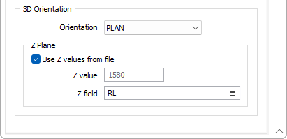
Z field
If you have selected the Use Z values from file option, select the field in the file that contains Z values.
The Line, Point, and Polygon tabs will only be enabled if the appropriate feature type has been selected in the Display Features group.
If needed, you can convert from geographic (Latitude and Longitude) coordinates by setting grid transformation parameters in the Coordinate Transform tab.
To display a text annotation layer, you must select the Points feature type. Microstation® DGN files and AutoCAD® DWG and DXF files are supported by this function.
You can also use the options on the File tab, in the Import group, to import GIS and GPS file formats. See: Vector (GIS/GPS) Data.
Forms
Click the Forms button to select and open a saved form set, or if a form set has been loaded, save the current form set.
By design, the Forms button is not available for loaded Vizex layers (i.e. when opening the form set properties of a layer in the Vizex Layer Display pane). In Vizex, the Forms button is only available for new forms opened via the Home tab or the Vizex tab, in the Layer group (or by double-clicking on a form type node in the Vizex Layer Types pane).
Save and Save As
Click the Save button to save the changes you have made to the form set. Click Save As to save your changes as a new form set. Save As will default to the first available form set number.
Reset
Click Reset to clear the form of all values and reset the form to its default state.
Reset Tab
For tabbed forms, select Reset Tab to clear the active tab of all values and reset the tab to its default state - without making any changes to other tabs in the dialog.
Undo and Redo
Click Undo (CTRL + Z) to undo recent changes in the form. After an Undo, click Redo (CTRL + Y) to restore the last change that was undone.
Collapse
Collapse (roll-up) the form to preview a chart, or preview the results of an operation in Vizex, or obtain input values from Vizex, the Property Window, the File Editor, or the Plot Editor.