Display
Use the options provided on the Display tab of the Oriented structure form to choose whether to display the True Dip or the Apparent Dip and control the length and the appearance of the displayed strings.
If the input file contains a code field that defines the structure, it can be used to colour code the display.
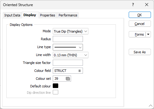
Mode
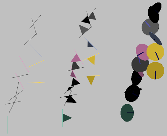
Select the Display mode. You can display the APPARENT DIP (with simple lines) or the TRUE DIP (with oriented triangles or discs).
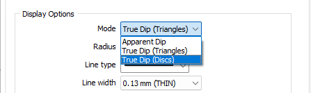
When you select APPARENT DIP as the display mode, a simple line is used to show the apparent dip of each structure. The apparent dip angle is a function of the true dip and the angle between the drill section line and the drillhole trace.
When you select TRUE DIP (Triangles) as the display mode, a triangle is used to depict the plane of each structure. The size of each triangle is determined using the specified radius (and optionally a triangle size factor) and the true dip value for each event. The greater the dip, the larger the triangle used to represent the plane.
When you select TRUE DIP (Discs) as the display mode, a disc is used to depict the plane of each structure. The size of each disc is determined using the specified radius. The greater the dip, the larger the disc used to represent the plane.
Radius
Enter a radius (in grid units) that will be used to represent the apparent dip or the line of strike of the true dip.
When the display mode is TRUE DIP (Triangles), the radius you specify is used with the true dip value (and optionally a triangle size factor) to determine the size of the triangle used to represent the plane of each structure.
When the display mode is TRUE DIP (Discs), the radius you specify is used to determine the size of the disc used to represent the plane of each structure.
Line type
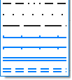
When you select APPARENT DIP or TRUE DIP (Triangles) as the display mode, you can select a line type. A preview of each line type is shown in the drop-down list. A variety of solid, dotted, and dashed line styles are available for selection.
Note: Extended line styles such as double lines are not compatible with 2D plots (they will render as a solid line) and will only display properly in Vizex and 3D Vizex plots (and screenshots). Extended line styles are displayed in blue in the Line Type drop down.
Line width
When you select APPARENT DIP or TRUE DIP (Triangles) as the display mode, you can select a (THIN, MEDIUM, THICK, or custom) line width from the drop-down list. An extensive selection of custom widths (in millimetres) are available for selection.
Triangle size factor
When you select TRUE DIP (Triangles) as the display mode, you can control the size of the triangles by applying a size factor to the size calculations. A factor of 2, for example, will double the size of the triangles generated by the process.
This input will be disabled when TRUE DIP (Discs) or APPARENT DIP is selected as the display mode.
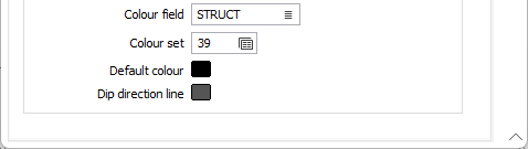
Colour field
Specify the name of a field which contains the values that will be used to colour-code the display.
You can choose to select colour values directly from the Colour field without selecting a Colour set. In this case, the values in the Colour field must be valid RGB, Hex, or Integer colour definitions.
| Format | Example |
|---|---|
| R,G,B | 89,169,215 |
| HTML Hex | #59A9D7 |
| Hex | 0x59a9d7 |
| int | 5876183 |
Colour set
To map values in the Colour field to the colour values in a Colour set, double click (F3) to select the set that will be used to control the display colour. Right-click (F4) to create or edit a Colour set.
Default colour
Double-click (F3) to select the colour that will be used when a Colour field or a Colour set is not defined - or when a value in the Colour field is either not valid or is not mapped in the Colour set.
Dip direction line
When you select TRUE DIP (Discs) as the display mode, you can select the colour of the line that indicates the dip direction.
Double-click (F3) to select the colour. If you prefer to hide the dip direction line, select the NULL colour.