Drillholes
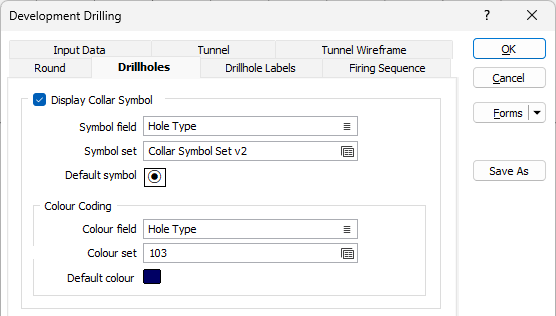
On the Drillholes tab of the Development Drilling form, specify the display characteristics and the types of hole to display.
Display Collar Symbol
Select this check box to set symbology and colour-coding options for each drillhole collar.
Symbol field
Specify the name of
Symbol set
Double click (F3) to select the set that will be used to determine the symbol that will be displayed. The symbol set maps symbols to text strings or numeric ranges. This determines a symbol for each value in the chosen (mapped)
Default Symbol
Double-click in the Default Symbol box to select the symbol to be used when a Symbol
Double-click the Symbol icon to choose a symbol. You can source symbols from any TrueType or OpenType font.
Colour Coding
Select this option if you want to colour code each collar based on the values in a colour field.
Select the field in the Database file that contains values which will determine the colour to be used to depict the collars. The colour set, that is associated with this field, maps colours to text strings or numeric ranges. For each record in the file, the display colour is determined by the value in this field.
Double click (F3) to select the colour set that will be used to control the display colour. The colour set maps colours to text strings or numeric ranges. This determines the colour for each value in the colour field. Right click (F4) to create or edit a colour set.
Double click the Default colour box to open the Colour Selection form and select a default colour.
Display Damage Zones
Select this check box to display a ring or circle around the hole(s) to represent damage zones. The Practical Damage Zone of each hole can be displayed for holes which possess a Radius of Damage value (optionally specified when adding drillholes to a round).

Colour Coding
Colour field
Specify the name of a field which contains the values that will be used to colour-code the display.
Colour set
Double click (F3) to select the colour set that will be used to control the display colour.
Default colour
Double-click (F3) to select the colour that will be used when a Colour field or a Colour set is not defined - or when a value in the Colour field is either not valid or is not mapped in the Colour set.
A transparency can be applied to ensure the zones do not obscure the rounds in the display.
Display Planned Holes
Select the Display planned holes check box to display the traces of holes.
The Line type drop down is used to select the type of line with which to display the planned holes. A preview of each line type is displayed in the list.
Set the Line width for the display using the drop down provided.
Select a default colour for the drillhole traces using the Uncharged colour box. Any part of a drillhole trace which does not contain any charge material will be shown in this colour.
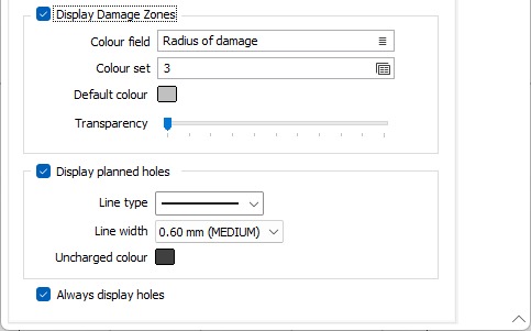
Uncharged colour
Double-click on the colour icon, to select a default colour for the drillhole traces using the Uncharged colour box. Any part of a drillhole trace which does not contain any charge material will be shown in this colour.
Always display holes
Select the Always display holes check box to specify that drillholes be displayed when working in Vizex. When this check box is disabled, the drillholes will only be shown when you are in Edit Round mode.