Display
Use the options provided on the Display tab to render your wireframe objects.
Draw Style
Select a Draw Style.
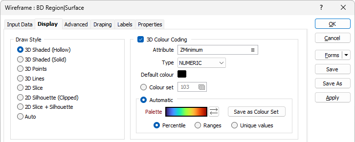
3D Colour Coding
Select this option if you want to colour code the wireframe layer based upon a wireframe colour attribute and either the colour values defined in a Numeric or Text colour set or the colours automatically applied form a chosen palette.
If the 3D Colour Coding check box is not selected, the wireframe colour is used.
Attribute
The Colour Attribute defaults to [Z] values. Alternatively, select a Numeric or Text assign type and then double-click (F3) to select an attribute that will be mapped to the colours you have specified below.
Default colour
Double click the Default colour box to select a colour to use by default for the wireframe.
Colour Set
Colour sets are one of the most important ways of making it easy to differentiate between values, regions and other objects in the display. The tools you can use to create colour sets (including the Automatic option below) are particularly powerful. Colour sets are saved as form sets and can be used anywhere in a project and can even be exported to other projects.
Choose whether wireframe attribute values will be mapped to the values in a NUMERIC or TEXT colour set.
Double-click the Colour Set input box if you want to select an existing colour set. Right-click in this box to edit the selected colour set or to create a new one.
Automatic
Select Automatic to select a palette and automatically apply colour ranges to the data. The Save As Colour Set button provides the option to save the result as a colour set.
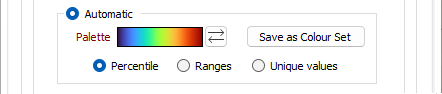
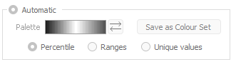
Choose a mode of calculation:
| Mode | Description |
|---|---|
| Percentile | The application will divide the data into ranges each containing the same number of values; the highest and lowest value in each bin will define the upper and lower values for each range. |
| Ranges | The data will be divided into equal ranges. |
| Unique values | A colour will be assigned to each unique value. |
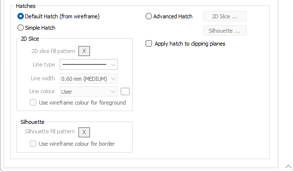
Default Hatch (from wireframe)
A 2D Slice and Silhouette hatch pattern can be saved as part of the wireframe. When displaying a wireframe, select Default Hatch to use these saved hatches. This can be particularly handy when displaying a wireframe set.
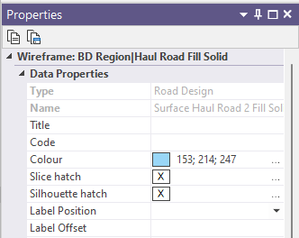
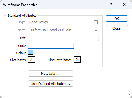
The default hatch (silhouette and slice) for any wireframe is NO FILL, with a solid, 0.20mm thick border using the wireframe colour. This default hatch is indicated by the NULL patch, in either the Property Pane (select the wireframe in Vizex) or the Wireframe Properties (right click on the Wireframe Name in any form):
If you want to revert to the default hatch, then open the Wireframe Properties dialog, click on the patch and press the DEL key (this is not supported in the Property Pane).
You can interactively change the Default Hatch (the hatch stored in the wireframe), by double clicking on the patch (to bring up the Fill Pattern dialog) and editing the hatch. When both the foreground and border colour are NULL (or foreground is NULL and the border colour is set to Use foreground), then the wireframe colour will be used for both foreground and border. In this case, the patch colour (in the Properties Pane) will be a light grey. However, in the Fill Pattern dialog itself the Sample will not be displayed and the patch in the Wireframe Properties will appear blank.
In Vizex the default hatch is honoured when Default hatch (from wireframe) is chosen as the display option.
When the display option is Simple hatch, then the default pattern can still be used by setting the fill pattern to NULL (this is done by pressing the DEL key when the patch has focus):
All the line (border) settings, for the displayed hatch, come from the values defined in the Simple Hatch group box.
Simple Hatch
There is a subtle distinction between a wireframe displayed in 2D Slice mode and a wireframe displayed in Silhouette mode. Silhouette mode always generates one or more polygons (closed strings), whereas 2D Slice mode may generate profiles (from open surfaces) and/or polygons (from closed surfaces or solids).
- 2D Slice display settings comprise a fill pattern (ignored when the wireframe is an open surface) and line style options (used to draw the profile when the wireframe is an open surface, and used to draw the border when the wireframe is a closed surface).
To clarify that border line options are defined separately, the Border group box has been removed from the Fill pattern dialog.
Fill pattern
Double-click on the Hatch icon to select a Select a hatch for a Silhouette, or for the 2D slice of a wireframe solid.
Line type
Select a line type. A preview of each line type is shown in the drop-down list. A variety of solid, dotted, and dashed line styles are available for selection.
Line width
Select a (THIN, MEDIUM, THICK, or custom) line width from the drop-down list. An extensive selection of custom widths (in millimetres) are also available for selection.
Line Colour
Choose how the lines are coloured:
| From Wireframe | Use the wireframe colour |
| From Pattern | Use the foreground colour |
| User | Enable the colour picker to the right of the drop-down list |
Silhouette
For a silhouette, line type, line width and line colour selections define the border style of the wireframe (or the profile line style for open surfaces).
In the case of a 2D Slice, line type, line width and line colour selections are exposed to allow the profile line style for open surfaces to be defined without selecting a fill pattern
Fill Pattern
Double-click on the Hatch icon to select a default Select a hatch.
Use wireframe colour for the border
Select this option to apply the wireframe colour to the silhouette border.
Advanced Hatch
Select the Advanced Hatch option to set the hatch for wireframes in 2D Slice and Silhouette display mode, using colour, line, and hatch sets. Advanced option will typically apply when the input is a wireframe set, rather than a single wireframe.
Since you might want to use the advanced options for 2D Slice and not Silhouette (or vice-versa), or for only one of the attributes (say foreground colour), there is provision to define default values for every attribute of the hatch.
Any option that is not selected, will be defined by the appropriate parameters on the main form. For example, if the Pattern option is not selected, then the pattern defined on the main form will be used.
Apply hatch to clipping planes
Select this option to apply a hatch to the clipping plane, when applicable.
If the draw style is 3D Shaded (Solid and Hollow), and the 2D Slice Hatch is selected, then that border line style and pattern (no fill for Hollow) will be used to draw the end cap when in Single Clipping Plane mode, and draw the nearest end when in Clipped view.

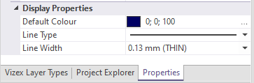
Note that some display properties may be viewed and edited in the Vizex Property Window: