Ring
On the Ring tab of the Ring Design form, specify the display characteristics of the holes and the ring boundary. You can also display reference string guidelines.
Ring
Display Ring name
If you want to display the ring name, select the Display name option to enable the display name Colour and Text Properties selection boxes.
Text Properties
Double-click on the Text Properties Preview box to select a font and set text properties for the labels.
Ring boundary
Set line type, line width, and line colour options for the ring boundary.
Line type
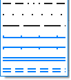
Select a line type. A preview of each line type is shown in the drop-down list. A variety of solid, dotted, and dashed line styles are available for selection.
Note: Extended line styles such as double lines are not compatible with 2D plots (they will render as a solid line) and will only display properly in Vizex and 3D Vizex plots (and screenshots). Extended line styles are displayed in blue in the Line Type drop down.
Line width
Select a (THIN, MEDIUM, THICK, or custom) line width from the drop-down list. An extensive selection of custom widths (in millimetres) are available for selection.
Drive and ring display settings are global and apply to all objects of the same type.
Colour
Double-click on the colour icon, to select a colour that will be used to display the ring boundary.
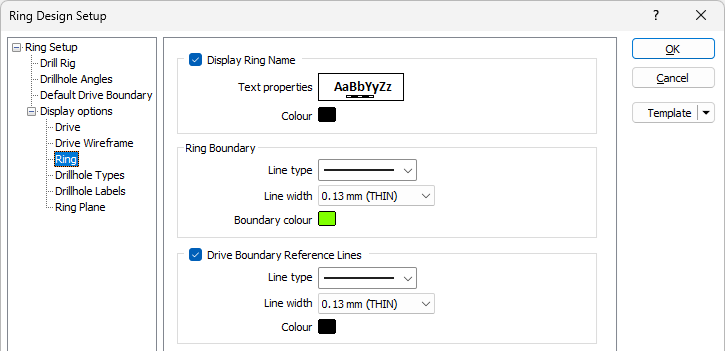
Drive Boundary Reference Lines
Select the check box to set line type, line width, and line colour options for reference guide lines which may be used to delineate the sections of the drive profile. In other words, the guide lines are used as a visual aid during the positioning of the drill rig within the bounds of the drive.
Line type
Select a line type. A preview of each line type is shown in the drop-down list. A variety of solid, dotted, and dashed line styles are available for selection.
Note: Extended line styles such as double lines are not compatible with 2D plots (they will render as a solid line) and will only display properly in Vizex and 3D Vizex plots (and screenshots). Extended line styles are displayed in blue in the Line Type drop down.
Line width
Select a (THIN, MEDIUM, THICK, or custom) line width from the drop-down list. An extensive selection of custom widths (in millimetres) are available for selection.
Colour
Double-click on the colour icon, to select a colour that will be used to display the guide lines.
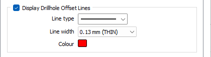
Display Drillhole Offset Lines
Drillhole offset lines can be added to the display as a visualisation aid when editing a ring. Set line type, line width, and line colour options for the offset lines.
Line type
Select a line type. A preview of each line type is shown in the drop-down list. A variety of solid, dotted, and dashed line styles are available for selection.
Note: Extended line styles such as double lines are not compatible with 2D plots (they will render as a solid line) and will only display properly in Vizex and 3D Vizex plots (and screenshots). Extended line styles are displayed in blue in the Line Type drop down.
Line width
Select a (THIN, MEDIUM, THICK, or custom) line width from the drop-down list. An extensive selection of custom widths (in millimetres) are available for selection.
Colour
Double-click on the colour icon, to select a colour that will be used to display the offset lines.
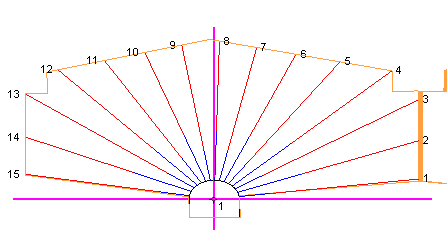
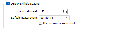
Display Drillhole Spacing
Select the Display Drillhole Spacing check box to display the distance between the holes on each ring.
Annotation set
Select an Annotation set (F2), right-click to Edit an existing set or right click to create a New annotation set, to set label options for the annotation distance between the holes.
Planned holes are displayed by default. If Display as-drilled holes is selected on the Drillhole Types tab of the Ring Design form and as-drilled holes exist, then the annotation distance will also be shown for as-drilled holes.
Use the Default measurement drop down to select the measurement to be used for the drillhole spacing by default.
If you select the Use fan own measurement option, the measurement for the fan will be used for drillhole spacing.

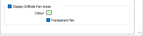
Display Drillhole Fan Areas
Select the Display Drillhole Fan Areas check box to apply a background colour to the fan area.
Select the Transparent fan option to display the drillhole fans as transparent.