Display
Use the settings provided on the Display tab of the Volume form, to set the appearance of the 3D Volume. 3D shading, volumes containing multiple slices, and isosurfaces are supported.
Note that the check box options in the associated grid lists are still enabled when the 2D Slices and Isosurfaces check boxes are NOT selected. This is because 2D Slice and Isosurface child nodes of the Volume are always created; the parent check box simply controls their visibility in the layer.
3D Shaded
Select this check box to display the volume in 3D where the block faces appear as solids.
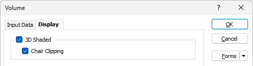
Chair Clipping
Geophysical models are often displayed such that one corner of the data is cut away to reveal the internal model composition.
Select this check box to create a 3D shaded volume with a clipped section. Note that it is currently only possible to toggle this option on and off via the form.
2D Slices
Select this check box to display volumes as a 2D Slice group. In section views, this group will draw a single slice on the section plane instead of drawing the individual slices. The grid is initially set to have X, Y and Z slices in the middle by default.
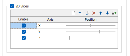
Enable
These check boxes determine whether the slices are active in the Vizex view or not (these can also be toggled in the Vizex Layer Display pane).
Axis
The Axis (X, Y, Z) setting determines which plane the slice is aligned to.
Position
The Position slider bar determines the location of the slices along their axes. Min/Max slider values represent opposite ends of the volume, the default position along each axis is middle. In Vizex, each slice can be interactively dragged to alter its position and this will update the Position values on the form.
Autofill
![]() Click the Autofill button on the grid list toolbar to generate a specified number of 2D Slices in the 2D grid list, all enabled and separated from one another by equal distances. See: Add 2D Slices
Click the Autofill button on the grid list toolbar to generate a specified number of 2D Slices in the 2D grid list, all enabled and separated from one another by equal distances. See: Add 2D Slices
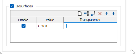
Isosurfaces
Select this check box to display isosurfaces as an Isosurfaces group.
Enable
These check boxes determine whether the isosurfaces are active in the Vizex view or not (these can also be toggled in the Vizex Layer Display pane).
Value
Enter a Cutoff value. One isosurface at a value of 0 is added by default.
Transparency
Optionally, use the Transparency slider to adjust the transparency of the isosurface. This allows multiple isosurfaces to be rendered over the top of one another.
In the Vizex Layer Display Pane, when an Isosurface is selected in the Isosurfaces group, the Property Window displays its Percentile, Transparency, and Cutoff values:
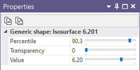
The values are adjustable via a slider. Any changes made here will update the values on the Display tab of the Volume form.