Display
On the Display tab of the CAD form, specify how native colours in the input file are handled. You can also select a draw style for solid/mesh CAD features.
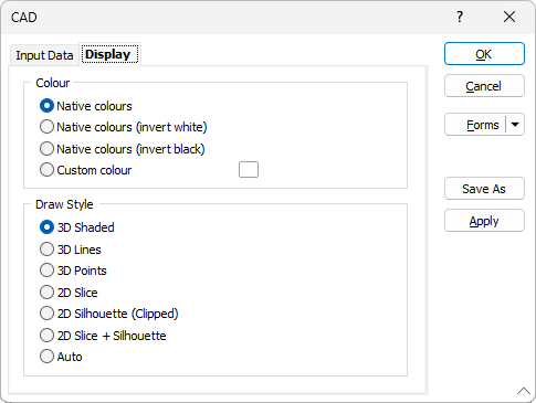
Colour
By default, native colours and style information are extracted from the Input file, including the colour, size and rotation of any text labels. You can also choose to invert white or invert black when extracting native colours.
Alternatively, select the custom colour option and click on the colour patch to select a colour.
You can also invert blacks when you:
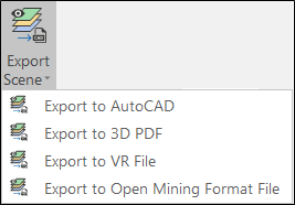
- Select Export to AutoCAD, on the Vizex tab, in the Capture group, to export the current Vizex scene to a CAD (.DWG, .DXF, .DXB) file format.
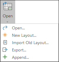
- Select Open > Export, on the Home tab or the Vizex tab, in the Plot group, to export a plot layout (.pex) file to a CAD file format.
Draw Style
Select the draw style to be applied to solid/mesh CAD features:
| 3D Shaded |
This is the default draw style for any wireframe that is auto-loaded in Vizex (as a result of a Wireframe Boolean operation for example). |
| When a clipping plane is used, if the slice through a wireframe forms a closed solid, a fill is automatically applied to the sliced section. | |
| If the draw style is 3D Shaded and a 2D Slice Hatch is selected, then that border line style and pattern (no fill for Hollow) will be used to draw the end cap when in Single Clipping Plane mode and the nearest end when in Clipped view. | |
| Note that 3D Shaded draw styles cannot be plotted. When plotted, they are drawn as 3D lines. | |
| 3D Lines | Select this option to view wireframes as 3D lines. |
| 3D Points | Select this option to view wireframes as 3D points. |
| 2D Slice | This draw style will generally use the least memory and be the quickest to draw. |
| When you select the 2D Slice draw style, a cross-section through the wireframes in the current layer is displayed in the plane of the current view - or the orthogonal plane that is closest to the plane of the current view. If, however, the current view is a transform section, then the actual plane of the view will be shown. | |
| When 2D Slice is selected the hatch icon is enabled, allowing a hatch or fill pattern to be applied to the cross-section. | |
| 2D Silhouette (Clipped) | Select this option to view wireframes in silhouette. Silhouettes are created for the current view direction and are only recalculated once any camera movement is finished. |
| Clipped indicates that, when the view is clipped, the silhouette is that of the wireframe within the clipping region (as opposed to the whole wireframe). | |
| 2D Slice + Silhouette |
See '2D Slice' and '2D Silhouette' above. |
| Auto | When the Auto option is selected, a 2D Slice draw style is applied when the current view is clipped. Otherwise, a 3D Shaded (Hollow) draw style is applied. |
Layer sub-shapes can be given their own draw style by right-clicking on the sub-shape in the Vizex Layer Display pane.