Targets
On the Targets tab of the Drillhole Fan Setup form, use the options provided to set the orientation and the extents of the grid pattern.
Project Targets on Wireframe(s)
Select this check box to project the collar points defined on the Collars tab of the form onto one or more surfaces or solids.
To process a single wireframe, select the Single option, select the Type of the wireframe, and then the Name of a wireframe of that type.
To process multiple wireframes, expressions, wildcards and partial names may be used in the Name field to select multiple wireframes as an adhoc wireframe set. A right-click Preview option will perform a check of an expression before using that expression to generate an updated list of wireframes. Alternatively, you can click the Expression icon ![]() and use the Expression Editor to create, modify and validate the expression. When a name or wildcard is entered in the Name field, and the Expression button is selected, the name/wildcard will automatically be converted to a valid expression when opened in the editor.
and use the Expression Editor to create, modify and validate the expression. When a name or wildcard is entered in the Name field, and the Expression button is selected, the name/wildcard will automatically be converted to a valid expression when opened in the editor.
To process the wireframes in a predefined wireframe set, select the Set option.
It is recommended that you Validate wireframes prior to using them in any process.
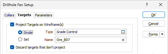
Discard targets that don't project
By default, targets that cannot be projected onto the wireframes based on the parameters specified on the Parameters tab of the form, are discarded from the fan creation process. If you prefer to visualise the target holes that cannot be projected before deleting them manually, deselect the check box to include them.
Target Gridding
Use the options in this group to calculate the orientation and the extents of the grid pattern.
From Wireframes(s)
When you have chosen to Project Targets on Wireframe(s) (above), the orientation and the extents of those wireframes are used to set the Dip and Dip Direction and the extents of the grid pattern.
From Working Plane
When you have chosen to Project Targets on Wireframe(s) (above), if a suitable display layer is open, the Dip and Dip Direction of the grid pattern is automatically filled from a working plane in Vizex (the button is disabled if there is no working plane defined).
From Points
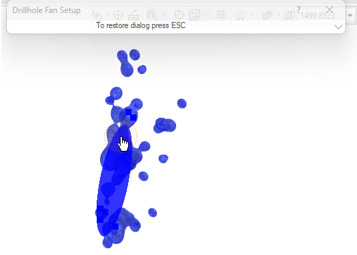
Click this button to collapse the form and interactively digitise points to create a search ellipsoid. The plane and the size of the ellipsoid is used to set the plane and the size of an initial grid pattern. Press ESC to return to the form.
Edit in Vizex
Click this button to collapse the form and interactively resize and orientate the grid pattern:
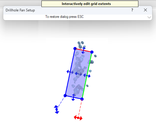
The X, Y Z dimensions and the orientation parameters of the grid pattern shown in the form are adjusted automatically. You can also manually adjust those parameters.
A Hole count is shown for reference purposes and this will change based on the specified grid extents and the hole spacing.
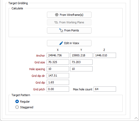
Target Pattern
Choose between a Rectangular or a Staggered grid pattern. The Staggered pattern is based on a diamond grid. The spacing distance usually ranges between 100% and 200% of the burden distance.
| Rectangular: |
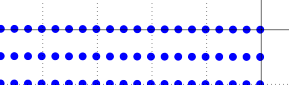
|
| Staggered: |
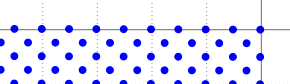
|