Drillhole Planning
On the Drillhole tab, in the Planning group:
-
Click Drillhole Planning to open the Drillhole | Planning ribbon and put the Vizex window in Planning mode.

-
Click Drillhole Planning | New Plan to create a new Drillhole Plan layer and open the Drillhole | Planning ribbon with Vizex in Planning mode.
-
Click Drillhole Planning | Open Plan to load and configure an existing file in the Planning form to open it as a Drillhole Plan layer in Vizex in Planning Mode.
-
Click Drillhole Planning | Load Drillholes Into Plan to load existing collar and survey data, or traces, into the active planning layer.

On the Drillhole | Planning tab, in the Layer group:
-
Click New to create a new Drillhole Plan layer in Vizex.
-
Click Open to load and configure an existing file in the Planning form to open it as a Drillhole Plan layer in Vizex.
-
Click Edit Form to open the form for the selected layer.

On the Drillhole | Planning tab, in the Planning group:
-
Click Drillhole Planning | Load Drillholes into Plan to load existing Collar and Survey data or Traces into the active planning layer.
-
Click From Collar to interactively design a curved or straight drillhole starting from the collar, then build the trace towards the target area.
![]()
-
Click From Target to interactively design a curved or straight drillhole starting from the target, then build the trace towards the collar.
![]()
-
Click Manual Hole to manually digitise a hole trace.

-
Click Create Pattern to generate a regular pattern of planned holes and add them to the planning layer. The holes of the pattern can be adjusted interactively.
![]()
-
Click Copy to Active Layer to copy selected drillholes to the active String layer.
![]()
-
Click Extend Hole to interactively extend an existing hole.
![]()
-
Click Reverse to reverse the order of the points on selected drillhole traces.

-
Click Finish Plan to save the planned holes. Holes are enumerated using a default “PDH001, 2, 3, etc“ identifier for each hole.
![]()
On the Drillhole | Planning tab, in the DTM group::
-
Click Extend and Clip to extend or clip drillholes so that the collar coincides with the DTM surface. The rest of the drillhole will not be moved

-
Click Drape to drape collars onto a DTM surface by repositioning the Z position of the collar to patch the DTM.

String Editing
Because the planned holes are strings, you can use relevant Vizex and String editing tools, like snapping to a target location or surface DTM, to assist with your design:
-
Click Enable Snapping (or use the S shortcut key) to enable or disable Snap mode.

-
Click the Gradient tool to set the gradient (and Gradient Units) for a selected string or segment.
![]()
-
Select Angle | 3D Angle / Distance to specify a bearing (azimuth) and a distance for the next segment when digitising a string. The distance is measured using the actual 3D distance (taking into account the elevation).
![]()
-
click Rotate Strings (Interactive), to rotate the strings and/or points you have selected in Vizex around a pivot point.

-
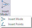
Click Insert Mode to toggle Insert Points mode on and off.

-
Click Dynamic Input to toggle Dynamic Input mode on or off when digitising strings or points. You can use the menu to switch between Cartesian Coordinates and Polar Coordinates input modes or select Relative mode to enter coordinates relative to the previous point. You can also press F12 to quickly toggle Dynamic Input on and off.
