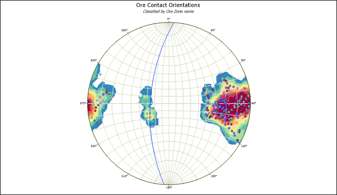
Stereonet
![]()
If you use Strike and Dip values, dips must be defined as positive for right dips and negative for left dips.
If you use Dip direction and Dip data values, the absolute values of dips are used.
Structures with a dip of 90 degrees will have their centres plotted on the stereonet boundary, meaning that a symbol may overlap the boundary.
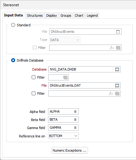
On the Input Data tab of the Stereonet Graph form, double-click (or click on the Select icon) to select the name of the Source file containing your data. The input file can be a standard data file or an Event file associated with a Drillhole Database.
Standard Input
Select this option if the data you want to display is contained in a data file. Double-click (or click on the Select icon) to select the name of the file. The following data file types are supported:

Optionally define a filter to restrict the process to a subset of the data in the file.
Drillhole Database Input
Select this option if the data you want to display is contained in an Event file associated with a Drillhole Database.
Double-click (or click on the Select icon) to select a Database from a list of the available databases in the current project. Select the Filter check box if you want to apply a filter to the database. Enter a filter number in the adjacent response. Double click (F3) to see a list of existing filters. Right click (F4) to open the dialog box where you can create a new filter.
File
Double-click (or click on the Select icon) to select the name of the event file containing your data. Optionally define a filter to restrict the process to a subset of the data in the file.
Alpha, Beta and Gamma
Where you have selected to Use Alpha, Beta and Gamma for Linear Structures, you can define the fields for the alpha, beta and gamma data using the fields provided.
Select Top or Bottom from the Reference line on drop down for the alpha, beta and gamma data.
Numeric Exceptions
(Optionally) Use the Numeric Exceptions group to control the way that non-numeric values are handled. Non-numeric values include characters, blanks, and values preceded by a less than sign (<).
Planar Structures
Select the Planar Structures check box to configure the Dip Direction/Strike and Dip field settings.
Use Alpha and Beta
Select this option to use Alpha and Beta angles in the Event file to define the orientation of the data, rather than use Strike/Dip Direction and Dip values. You will need to define the Alpha and Beta fields and set the Reference line orientation in the Drillhole Database Input group.
- Specify the field containing the Alpha angle, or core bedding angle. This is a measurement of the dip of the planar surface relative to the core axis.
- Specify the field containing the Beta angle. This is the clockwise angle measured from the orientation (reference) line, to the bottom point of the planar surface on the core. See: Oriented Core
- Use the Reference line on drop down to select whether the reference line (the reference for the Beta Angle measurement) is marked along the Top or Bottom of the hole.
Dip field
Double-click (or click on the List icon) to select the name of the Dip field.
Either:
- Select the Dip direction field option and double-click (or click on the List icon) to select the name of the Dip direction field, or
- Select the Strike field option and double-click (or click on the List icon) to select the name of the Strike field.
You can use either Strike and Dip or Dip direction and Dip data, but not both types at the same time. The choice depends on tradition, but the aim should be for consistency in the displays.
Linear Structures
Select the Linear Structures check box to configure the input for linear structures.
Use Alpha, Beta and Gamma
Select the Use Alpha, Beta and Gamma option to use the alpha, beta and gamma angles in the Event file to define the orientation of the lineation data, rather than the Plunge and Trend values. This option is not available if the Standard option is selected.
The Alpha and Beta measurements define a plane and the Gamma measurement defines the pitch of lineations on that plane. If you select this option, you will need to define the Alpha field, Beta field and Gamma field in the Drillhole Database Input group.
If you select the Show planar structures containing lineations option, planar data containing lineations will be shown. If the Planar Structures option is not selected, this option is disabled and planar data will not show.
Use Plunge and Trend
Select the Use Plunge and Trend option to configure the Plunge field and Trend/Azimuth settings.
Select the Plunge field for the stereonet graph using the List icon
Select the Trend field for the stereonet graph using the List icon..
Structure Classification
Code field
Use the selection button in the field to select a Code field for the stereonet graph.
Planar code
Use the Planar code field to select a planar code for the stereonet graph.
Linear Code
The Linear code field is used to select the linear code for the stereonet graph.
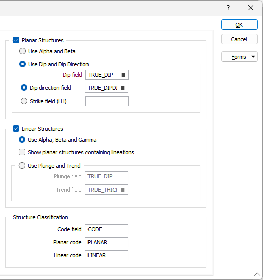
OK
When you have set Display options and Groups for the graph, click OK to generate and View the Stereonet.