Drape onto Wireframe
![]()
This option is also available from the Drape tool on the Design tab, in the Editing group.
For example:
-
When digitising a pit, you may want the batters to match with the slope of a coal seam, and then build the pit outline at the same inclination rather than start from a flat base.
-
When digitising a waste dump or a stockpile, you may want to drape the base string over a DTM of the ground surface.
You can only drape strings onto a wireframe using this form. To drape outlines or points onto a wireframe, use the interactive tool on the String Tools (Strings | Tools) toolbar. See: Drape on Wireframe
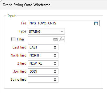
Input
File
Select a file type and double-click to select an input file. If required, define a filter to selectively control the records to be processed.
If you select the Filter check box, you can select an existing filter or create one using the Expression Editor by clicking the icon.
Easting and Northing (and Z)
Specify the names of the fields in which Easting, Northing, and (optionally) Z coordinates are stored in the input file.
Join field
Specify the name of the field that will contain values that define whether data points will be joined by a line i.e. strung. If successive records have the same value in this field and no String field is defined (see below) a line will join the points. If a String field is defined, then values in each field in successive records must be the same before the points will be strung.
String field
Specify the name of the field containing values that define whether data points will be joined by a line. The values of this field in successive records must be the same before the points will be strung.
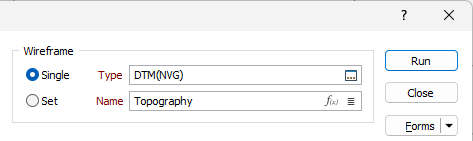
Wireframe
To process a single wireframe, select the Single option, select the Type of the wireframe, and then the Name of a wireframe of that type.
To process multiple wireframes, expressions, wildcards and partial names may be used in the Name field to select multiple wireframes as an adhoc wireframe set. A right-click Preview option will perform a check of an expression before using that expression to generate an updated list of wireframes. Alternatively, you can click the Expression icon ![]() and use the Expression Editor to create, modify and validate the expression. When a name or wildcard is entered in the Name field, and the Expression button is selected, the name/wildcard will automatically be converted to a valid expression when opened in the editor.
and use the Expression Editor to create, modify and validate the expression. When a name or wildcard is entered in the Name field, and the Expression button is selected, the name/wildcard will automatically be converted to a valid expression when opened in the editor.
To process the wireframes in a predefined wireframe set, select the Set option.
It is recommended that you Validate wireframes prior to using them in any process.
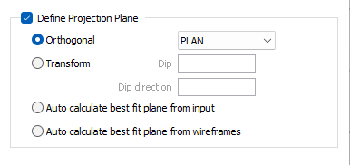
Define Projection Plane
Specify an Orthogonal (LOOKING WEST, LOOKING NORTH, PLAN) or Transform projection plane that will be used to define the direction in which the clipping string or outline will be stretched to create an open surface.
If you select the Transform option, enter the Dip and Dip Direction values that will be used to calculate the transformation.
Auto calculate best fit plane from input
Select this option to calculate the best plane of fit from the active (input) layer in Vizex.
Auto calculate best fit plane from wireframes
Select this option to calculate the best plane of fit from the specified wireframe.
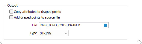
Output
Copy attributes to draped points
Select this option to copy the attributes of the strings in the input file to the records that are created for the draped points.
Add draped points to source file
If this option is selected, the draped points will be added to the source file and the Output file prompt will be disabled.
If you have chosen not to add draped points to the source file, specify the type and name of an Output file. The draped points will be written to this file.