3D Angle / Distance
![]()
Note: For Underground Mine Design, this tool is known as 3D Bearing & Distance and is located on the Mining | Underground Design tab, in the Modify group:
(You can also select a 2D Angle and Distance option from the tool menu. See: 2D Angle Distance)
If no strings are selected, the Selection Assistant prompts you to select the string(s) you want to apply a bearing and distance calculation to. When you select one or more strings and accept the selection, the Angle and Distance form is displayed.
Use this form to specify a bearing (azimuth) and a distance for the next segment when digitising a string. The distance is measured using either the horizontal or the vertical (projected onto the plane) distance, or the actual 3D distance (taking into account the elevation). Specify a gradient value and the units in which the gradient is measured.
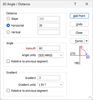
Distance
The distance for the next segment can be measured using:
- Slope distance (taking into account the elevation)
- Horizontal distance (projected onto the screen plane)
- Vertical distance (projected onto the screen plane)
Distance
Enter the distance to which the string(s) will be extended (in grid units).
Angle
Azimuth
Enter the Azimuth that will be applied to the next string segment.
Azimuths are expressed in decimal degrees, with zero (0°) being grid North. Negative values (anti-clockwise direction) and values greater than 360° are correctly evaluated.
Angle units
Select the format to be used for the Angle Units.
Relative to previous segment
If this option is selected, the azimuth of the next string segment will be measured relative to the azimuth of the previous segment, instead of relative to grid North (0°).
Gradient
Specify the gradient of the next segment. If the Gradient value is zero or is empty when in “1 IN ?” mode, the generated line segment will be horizontal (non-sloping).
In Screen Plane mode, the gradient is used to define the angle (instead of the bearing) since the gradient implies a change in Z values. "Z" is the screen up (2D Y axis) in Screen Plane mode.
Gradient units
Select the (1 IN ?, PERCENT, DEGREES, GRADIENT) in which the gradient is measured. See: Gradient Units
Relative to previous segment
If this option is selected, then the gradient is calculated as the sum of the gradient of the previous segment and the gradient value entered in the form.
Add Point
Click the Add Point button to add successive points at the bearing and distance specified.
Undo
Click the Undo button to undo the last addition.
Close
To close the form, click the Close button.
Forms
Click the Forms button to select and open a saved form set, or if a form set has been loaded, save the current form set.
Manage
To save the types, attributes and names you have defined and re-use them in other functions, select Manage button to create a form set or load an existing form set.
Save
Click Save to save your changes as the default form set.
Save As
Click Save As to save your changes as a new form set.
Reset
Click Reset to clear the form of all values and reset the form to its default state.