Add Holes on Line
![]()

The Add Drillhole on Line tool can be used to add a group of drillholes on a lines. The exact location and spacing of the holes will be based on the selected hole insertion methods. This tool can also be used to apply look-out to the holes that are added.
-
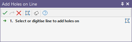
If not already selected, you will be prompted to select the line you want to add holes on:
-
Either select a line you have already digitised and click Accept to continue, or use the mouse to digitise a line that runs across the round.
On the application title bar, or the Quick Access Toolbar, click Undo (CTRL + Z) to undo the last edit. The Undo function records the edits you have made and will undo those edits in reverse order. Following an Undo, click Redo button (CTRL + Y) to re-apply the last edit.

Hole Spacing
Method
-
Fixed Spacing: The first hole is added at the first point of the selected line. The spacing between all subsequent holes will be fixed to the specified spacing value. When a fixed spacing method is applied, the last hole may not be located at the last point of the line.
-
Target Spacing: A hole will be added at both the first and last points of the line. Intermediate holes will then be fitted between these holes with a spacing that is as close to the specified value as possible.
-
Number of Holes: The specified number of holes will be added with a hole at both the first and last points of the line.
Spacing
Enter the spacing between holes to be added when the selected method is set to Fixed or Target Spacing.
Number of holes
Enter the number of holes to be added when the selected method is set to Number of Holes.
Measure distance along line
When this check box is selected, the distance between adjacent holes is based on the distance measured along the digitized line. When this check box is not selected, the distance is based on the distance of a tangential line between adjacent holes.
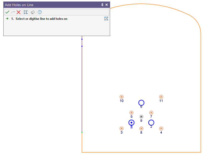
Figure 1 shows an example of when the Measure distance along line check box is disabled. In this example, the selected line was digitized along the roof of the heading. The Method is set to Fixed Spacing and the Spacing is set to 1.2. A preview of the holes given the design parameters is also shown.

Figure 2 shows the location of the second hole given each state of the check box. The dotted green line represents the tangential line used to measure the spacing between the first and second hole created when the check box is disabled. Therefore, a hole would be added at the last point of the dotted green line when the check box is disabled.

If the check box is enabled, then the spacing distance would be measure along the purple dotted line and a hole would be added at the last point of the dotted purple line.
Hole Details
Hole Type
Used to select the relevant hole type to be added on the line from the available list of Hole Types.
Diameter
Enter the diameter of the drillholes to be added. Hole diameter is a fundamental factor in blast geometry since it affects the results that can be achieved from blasting.
Length
Used to enter the length or depth of the hole.
Subdrill
Enter the length of sub-drilling required. When a subdrill value is specified, the total length of the hole will be equal to the Length + Subdrill. Note: Subdrill is normally positive (so the hole extends below floor level). Negative values are not allowed. See: Sub-Drilling
Lookout
Enable this check box if you wish to apply lookout to the drillhole(s) being added. Holes are added relative to the digitized line based on a specified distance and radio button selection.
Distance
Enter the lookout distance. The toe position of hole(s) is determined by offsetting the toe relative to the selected line segment by specified distance.
Left of Line
Holes are added relative to the digitized line. Select this radio button to add holes on the left side of the line.
Right of Line
Select this radio button to add holes on the right side of the line.
Direction
Select this radio button and enter an angle to offset the toe of hole(s) by the specified angle.
Note: A value of 0 is assumed if the distance or direction field is left empty.
Charge Details
Radius of Damage
Specify a practical radius of damage value. This value will be assigned to the Radius of Damage property of each drillhole that is added.
Charge Template
Optionally, double click in this field to select a charge template for the drillhole(s) being added to the round. See: Assign Charge Template
Show practical damage zone
Select this check box to show a damage zone for the hole, applying the value set in the Radius of Damage field.