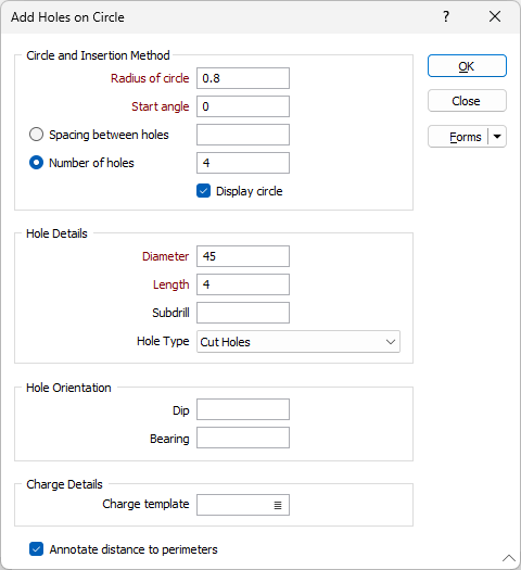
Add Holes on Circle
For example, Add Holes on a Circle can be used to add holes to a circular round of a shaft or vertical raise.

![]()
Circle and Insertion Method
Specify the Radius of the circle whose circumference you want to add holes around.
The Start Angle option lets you control the position of the first hole that is added on the circumference of the circle. An angle value of 0 corresponds to North of 12’ o’clock.
You can either specify a spacing between the holes (in degrees) or specify the number of holes to add around the circumference.
The option to display the circle is provided. Enable this check box if you would like to display the circle (dotted lines) whilst holes are added to the round.

Hole Details
Set the parameters of the holes you want to add:
Diameter
The diameter of the drillhole. Hole diameter is a fundamental factor in blast geometry since it affects the results that can be achieved from blasting.
Length
The length or depth of the hole.
Subdrill
If blastholes are to be drilled below the design length, enter the length of sub-drilling required. When a subdrill value is specified, the total length of the hole (Length field reported in the Drillholes List & Properties window) will be equal to the Length + Subdrill specified in the Add Drillhole form. Note that Subdrill is normally positive (so the hole extends below floor level). Negative values are not allowed. See: Sub-Drilling
Hole Type
Select the type of the hole you want to add. See: Hole Types
Hole Orientation
The Hole Orientation settings adjust the orientation of the holes.
The Dip value results in rotation of the drillhole about the X-axis in the Round Editor window. Dip value can be between -90 and 90 degrees. The following images illustrate hole with a dip of 10 degrees shown in the Round Editor window (left) and Vizex (right).
|
|

|

The Bearing value results in rotation about the Y-axis in the Round Editor window. Bearing value can be between 0 to 360 degrees.
Charge Details
Charge group
Optionally, double click in this field to select a charge template for the drillhole(s) being added to the round. See: Assign Charge Template
Annotate distance to perimeters
Select this check box to display dynamic annotations which report distances from a hole to the bounds of the round.