Output
On the Output tab of the Wireframe Pierce Points form, specify whether the output will be written as Events or as Intervals.
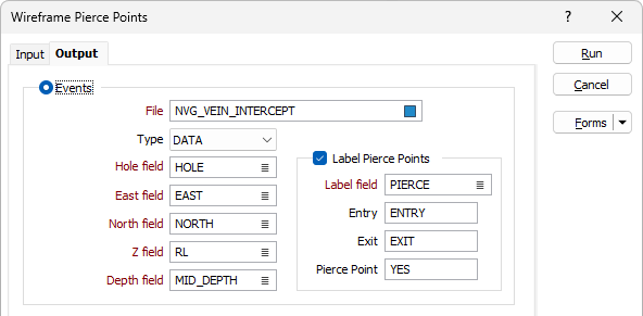
Events
If the Output mode is "Events", an Output file is generated that contains all the points where drillholes or strings intersect a wireframe or a wireframe set. The wireframe TYPE and NAME, DIP and DIP DIRECTION can be written to the Output file for each event.
File
Select a file type and enter (or double-click to select) the name of an Event file. The coordinates of each pierce point, a Hole ID (if applicable), and a Wireframe Name, will be written to the file.
Hole/Name field
This prompt will change depending on the Input type:
- If the Input type is Drillhole, double-click to select the Hole field that will be used to identify each pierce point.
- If the Input type is String, optionally double-click to select a Name field that can be used to identify each pierce point.
Easting, Northing and Z fields
Specify the names of the fields that will contain the Easting, Northing, and Z coordinates of each pierce point.
Depth field
Double-click to select the name of the field that will contain the depth of each pierce point.
Code Field and Labels
If the output mode is "Events", label values can be specified for the different (Entry, Exit, Pierce Point) pierce codes. However, if the input wireframe is an open surface, piercings can only be labelled as pierce points.
Code Field
Double-click to select the name of the field that will contain the pierce codes and enter the (Entry, Exit, Pierce Point) pierce code values.
Intervals
If the Output mode is "Intervals", an Output file is generated that contains a FROM-TO value (and optionally a wireframe TYPE and NAME) for each piercing. Intervals are added to the file whenever a hole or a string enters AND exits a closed solid. Piercings through an open surface are ignored.
If a hole or string begins within a wireframe then the first interval will have a FROM value of zero.
If a hole or string ends within a wireframe then the last interval will have a TO value = end of hole/string depth.
File
Select a file type and enter (or double-click to select) the name of the output file. The From and To depth of the entry and exit points, a Hole ID (if applicable), and a Wireframe Name, will be written to the file.
Hole/Name field
This prompt will change depending on the Input type:
- If the Input type is Drillhole, double-click to select the Hole field that will be used to identify each pierce point.
- If the Input type is String, optionally double-click to select a Name field that can be used to identify each pierce point.
From and To Fields
Specify the names of the fields that will contain the From and To depth values for the entry and exit points.
Output user-defined attributes
Select this check box option to write all user-defined wireframe attributes to the Output file. This option applies to both (Events and Intervals) output modes.

Add output to the drillhole database
When the Wireframe Pierce Points input is a Drillhole Database, select this check box to add the output file (Event or Interval) to the drillhole database.
In many cases, it may be useful to store the results of the pierce points process to the database that the input interval or event file is associated with. This aids in visualisation, making it easier to display related data in Vizex.
Auto load
Select the check box to automatically load the output file in Vizex.
With the option enabled, the following will occur:
-
For Intervals - A hatch layer is loaded with the Colour field set to the To field. If a Wireframe name field is provided, it will be used as the Colour field value and the Colour palette will be set to Discrete-Bright with Unique assignmentenabled.
-
For Events - There are various ways in which the Autoload option will run based on which fields are provided. In order of priority, these are:
-
If Label Pierce Points | Dip and Dip Direction are provided, an Oriented Structure Shape will be autoloaded.
-
If Events | Label Pierce Points | Label Field is provided, an Events Shape will be autoloaded with the Label Field being used in the Events Shape colour Field
-
If Label Pierce Points | Wireframe Name Field is provided, an Events Shape will be autoloaded with the Wireframe Name Field being used in the Events Shape colour field.
-
If none of the above fields are provided, then the Events Shape will be loaded using the default colour for symbols.
This order of priority means that if the fields for a method are not provided, the next method will be used instead.
-
The Auto load option will only be available if Add output file to the drillhole database has been selected.
Label Pierce Points
Select this check box option to label the pierce points with standard (Type and Name) wireframe attributes and, if the Events output mode is selected, the Dip and Dip Direction of the pierced triangles.
Enter (or double-click or click the List icon select) the name of the fields that will be populated in the Output file.
Output user-defined attributes
Select this check box if you want the attributes you have defined to be used in the label pierce point output. See User Defined Attributes.
