Pierce Points
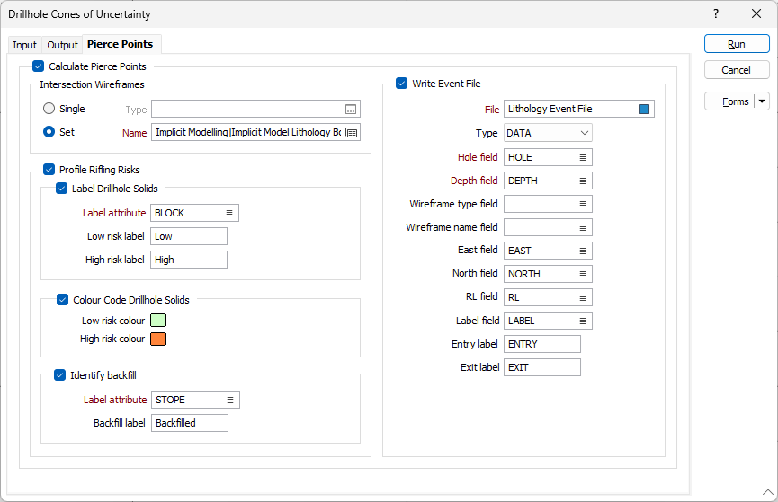
On the Pierce Points tab of the Drillhole Cones of Uncertainty form, you can specify the wireframe(s) which are evaluated for intersections with the drillholes. When this is done, an event file reporting the pierce points can optionally be created.
The tab also provides settings for optionally labelling the solid cones according to their risk of rifling.
Calculate Pierce Points
On the Pierce Points tab of the Drillhole Cones of Uncertainty form, select this check box to enable the options on the Pierce Points tab.
Intersection Wireframe
To process a single wireframe, select the Single option, select the Type of the wireframe, and then the Name of a wireframe of that type.
To process multiple wireframes, expressions, wildcards and partial names may be used in the Name field to select multiple wireframes as an adhoc wireframe set. A right-click Preview option will perform a check of an expression before using that expression to generate an updated list of wireframes. Alternatively, you can click the Expression icon ![]() and use the Expression Editor to create, modify and validate the expression. When a name or wildcard is entered in the Name field, and the Expression button is selected, the name/wildcard will automatically be converted to a valid expression when opened in the editor.
and use the Expression Editor to create, modify and validate the expression. When a name or wildcard is entered in the Name field, and the Expression button is selected, the name/wildcard will automatically be converted to a valid expression when opened in the editor.
To process the wireframes in a predefined wireframe set, select the Set option.
It is recommended that you Validate wireframes prior to using them in any process.

Rifling Risk Profiling
Rifling risk profiling illustrates the risk of rifling caused by deviated drillholes that intersect either filled or unfilled underground workings.
Note on the logic used to categorise risk
-
If a drillhole’s uncertainty cone intersects a filled solid twice, then this is an indication that the hole intersects the solid in a way that reduces the overall risk: There is a lower risk that a blast in a lower level could cause rifling up the hole (because the hole would end in the fill, which would prevent rifling). In such cases, the cones would be categorized as "low risk".
-
If a drillhole’s uncertainty cone intersects an unfilled solid twice (e.g. an unfilled stope or development tunnel), then the risk is high. In such cases, the cones would be categorized as "high risk".
-
Finally, if a hole intersects an unfilled solid once, then it is "low risk".
Select the Profile Rifling Risks check box to enable the Label Drillhole Solids options.
The Label Drillhole Solids check box enables the options to let you generate labels to differentiate between Low risk and High risk pierce points.
Enter an attribute name or double-click the Label attribute field to select the attribute to be labelled low risk or high risk. When you enter an attribute name, an attribute of that name is created.
Enter the Low risk label and High risk label values.

Colour Code Drillhole Solids
If you select the Colour Code Drillhole Solids check box, you can set the display colours for Low risk colour and High risk colour.

Identify Backfill
The Identify Backfill check box should be selected if you need to identify backfill within your pierce points wireframe. When the check box is disabled, the tool assumes that the input wireframes contain void.
Enter an attribute name or double-click in the Label Attribute field to select the relevant attribute for the backfill label. When you enter an attribute name, an attribute of that name is created.
Enter the Backfill Label in the field provided.

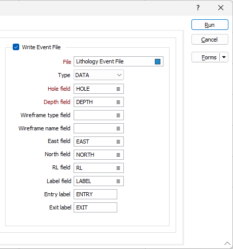
Write Event File
The Write Event File check box enables the write event values for the pierce points.
Use the File field to select the interval file. You can set the Type of file with the drop down.
Double-click the Hole field to select the field from the file that represents the hole.
Set the field to be used for the downhole depth of each pierce point using the Depth field.
The Wireframe type and Wireframe name can be set using the fields provided.
The East, North and RL fields are used to set the names of the fields that will be used to store the coordinates of each pierce point.
Double-click the Label field to select the field in the file which represents the pierce points label.
Enter the relevant label values for the Entry and Exit pierce points in the fields provided.
Determination of Intersection Depths
In the below image the yellow figure represents a cone generated around a drillhole trace (solid black line segments). The circular figures represent input solids being evaluated for intersections. To determine the intersection depth the function finds the closest points on the trace line to the given intersection vertex and interpolates the depth between the segment's start and end. The highest depth will be reported as the entry point and the lowest as the exit point.
The following diagrams illustrate how the tool identifies the points at which the cone and the wireframes intersect.

