Rotate
![]()
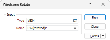
Input Wireframe
Specify the type and name of the input wireframe.
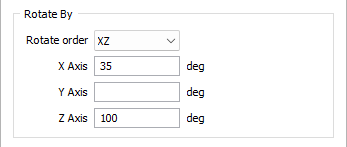
Rotate by
Enter a rotation value for each X, Y and Z axis of rotation, in decimal degree (DDD.DDDD) format. DDD.DDDD is degrees and decimals of a degree. A longitude value of 123° 7' 54.648'' for example, is written as 123.1318.
The terminology used in the application describes 'left-handed' rotations.
To visualise the handedness of these rotations, imagine grasping each axis with your left hand, with your thumb pointing along the positive direction. The direction in which your fingers curl indicates a positive rotation.
So, beginning with a rotation around the Z-Axis (what we would call an Azimuth rotation), grasping the axis with your left hand in a thumbs-up gesture (thumb pointing in the positive Z-direction), will result in your fingers curling around to the right. Thus, a positive rotation is to the right.
The same with a rotation around the X-Axis (what we would call a Plunge rotation); this time the thumb of your left hand points to the right and your fingers curl downwards and away from you.
The Y-Axis is trickier but works the same way. This time you hold your left hand as if you were stabbing something with a sword. Your thumb will point directly away from you and your fingers will curl downwards to your left.
Rotation Order
If more than one rotation axis is defined, the Rotation Order control is enabled. Select an option from the drop-down control to define the order of rotation.
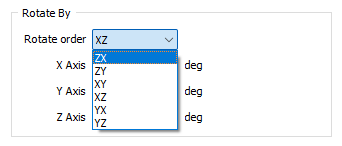
If an (X, Y or Z) rotation is undefined, it is treated as being 0.
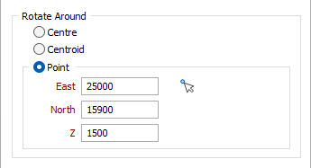
Rotate around
Specify the point around which the wireframe object will be rotated:
- Centre - The centre of the bounding box that defines the extent of the object.
- Centroid - The centre of gravity of the object.
- Point - A user-defined point. If this option is selected, enter the X,Y,Z coordinates of the point or use the Pick Point in Vizex button to select the coordinates from the active layer.
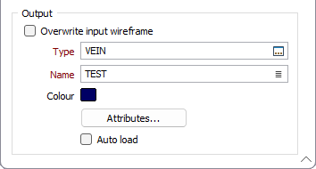
Output Wireframe
Select the Overwrite input wireframe option if you want the result of the process to be applied to the Input wireframe/s.
If the Overwrite input wireframe option is selected for a wireframe Set, all input wireframes are overwritten with their cleaned counterparts. If the option is not selected, the output Name is disabled and new wireframes are created for the output Type with the same name as their inputs.
If the Overwrite input wireframe is not selected for a Single wireframe, a cleaned output wireframe will be created and the input wireframe will not be overwritten.
If the option is not selected for a Single wireframe and an ad hoc Set is specified, new wireframes are created in the output Type. Names for these are provided by the output Name field, followed by an underscore “_” and the name of the input wireframe from which they came.
Output
Type and Name
Specify the type and name of the Output wireframe.
Colour
Specify a default display colour for the Output wireframe.
Attributes
Click the Attributes button to set Wireframe Attributes for the wireframe output.
User-defined attributes may be mapped against the fields in the Input file. It is also possible to specify a default value for each attribute. Default values are used when a corresponding value in the Input file is either missing or is not mapped.
Auto load
Select this option to load the generated output in Vizex. The default draw style for an auto-loaded wireframe is 3D Shaded.
Forms
Click the Forms button to select and open a saved form set, or if a form set has been loaded, save the current form set.
OK
Finally, click OK to begin the process.