Semi Variogram Parameters
A semi variogram model is said to have anisotropy if the range of the semi variogram differs with direction. The anisotropy defines the way that the Cross Validation and Kriging weights are applied. It does not affect the way the modelling process actually searches for data.
There are two ways to specify semi variogram model parameters:
- By selecting a Variogram Control File.
- By loading a Semi Variogram Model Form Set for each direction:
Variogram Control File
A Variogram Control File can be saved on the Chart | Variograms tab once a Variogram Map or Variograms Chart has been calculated, and provides a way of passing variogram information between different Variography functions or any function that need to reference a semi variogram as part of its modelling parameters.
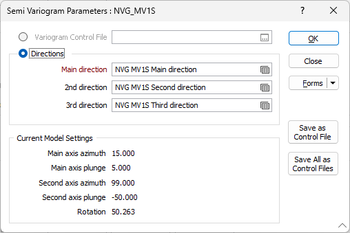
Directions
Main, 2nd, 3rd directions
You must specify variogram model parameters for the main direction. Model parameters for the second and third directions may also be specified.
To modify an existing set of Semi Variogram Model parameters, press F4 in the Direction prompt (or right-click and select Edit from the context menu.
To create a new set, right-click in the Direction prompt. If you are replacing an existing set, select New from the context menu.
To load a saved set, press F3 in the Direction prompt.
Current Model Settings
The Main Axis Azimuth and Second Axis Plunge defined for the main direction, are displayed for quick reference.
When modelling LINEAR or GENERAL LINEAR semi-variograms, the global variance of the input data must also be specified. This can be obtained from the information bar at the right of the screen while interactively modelling the semi-variogram.
Because linear and general linear semi-variograms have no sill and consequently no range, an alternative value must be used for an anisotropic model (i.e. two or three mutually orthogonal semi-variograms containing different parameters).
The application uses the global variance to back-calculate a pseudo-range at the point where the graph crosses the input variance, which is then used to calculate the anisotropy ratios.
The Save As Control File button is used to save the variogram control file to path, then change the form to use this file.
The Save All as Control Files button is used to save all variogram control files, based on all the form sets saved in the current project, to a specified folder location.