Show Guidelines
![]()
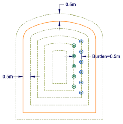
The Show Guides tool allows you to display or hide Guidelines. Guidelines are lines that can be used as an aid during the design process. For example, you may use guidelines to delineate the different parts of a round, the location of drillhole rows, or burden distances between adjacent rows.
Guidelines can be configured via the Edit Guides option or by double-clicking on the Guide layer of a round in the Vizex Display Pane.
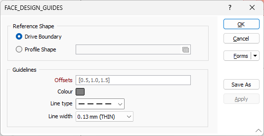
A set of guidelines can be based on a Drive Boundary shape of a given round (for example, when working with As-blasted tunnels) or another Profile Shape.
Reference Shape
Specify whether the guidelines will be positioned from points along the Drive Boundary or a Profile Shape.
Drive Boundary
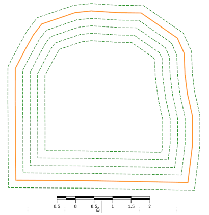
The boundary of the round is used as the reference shape from which guidelines are drawn. This option may be particularly useful when working with As-blasted data. In the below, an As-blasted tunnel has been added to the database. If the user prefers to see guidelines based on the as-blasted drive boundary, then the Drive Boundary option can be selected. Alternatively, the user can still show guidelines based on another Profile Shape.
Profile Shape
Enable this check box if you wish to use a custom profile shape as the reference shape. When this option is enabled, you can define a profile with custom dimensions, and use this as the reference shape from which guidelines are drawn.
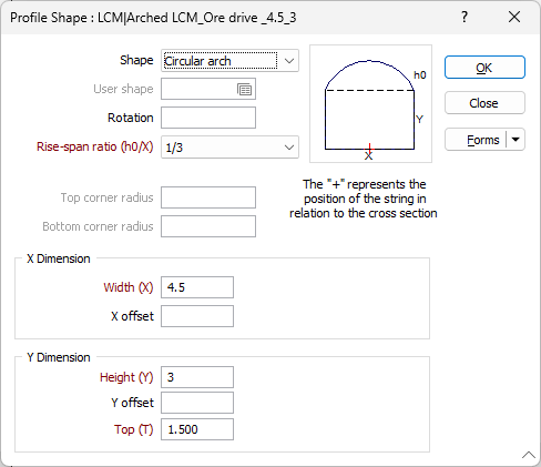
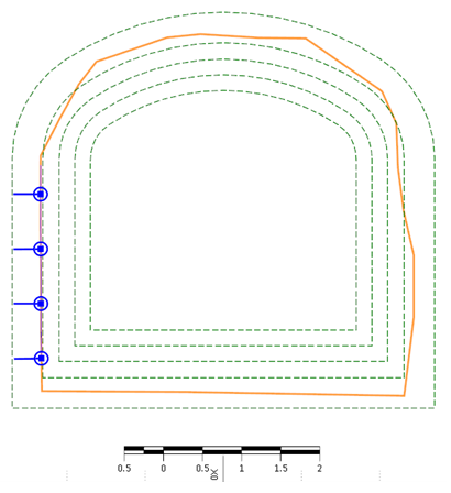
Using a Profile Shape as the Reference Shape for the Guidelines, results in the following example.
 .
.
If you have chosen the latter, click on the Form Set icon to load a profile shape form set.
Guidelines
Offsets
Offset values correspond to the spacing or offset distance from a guideline to the bounds of the reference shape. A negative value will produce a line outside the bounds of the reference shape, while positive values will produce lines insides the bounds of the reference shape. Each value entered in the Offset field should be separated from the next value with a comma (,) for example: 0.2,0.2,0.3,0.4,0.5.
Accept the default offsets or enter custom offsets for the lines to be displayed.
Colour
Double-click on the Colour icon to select a display colour for the lines.
Line type
Select a line type. A preview of each line type is shown in the drop-down list. A variety of solid, dotted, and dashed line styles are available for selection.
Line width
Select a (THIN, MEDIUM, THICK, or custom) line width from the drop-down list. An extensive selection of custom widths (in millimetres) are available for selection.

Forms
Click the Forms button to select and open a saved form set, or if a form set has been loaded, save the current form set.
By design, the Forms button is not available for loaded Vizex layers (i.e. when opening the form set properties of a layer in the Vizex Layer Display pane). In Vizex, the Forms button is only available for new forms opened via the Home tab or the Vizex tab, in the Layer group (or by double-clicking on a form type node in the Vizex Layer Types pane).
Save and Save As
Click the Save button to save the changes you have made to the form set. Click Save As to save your changes as a new form set. Save As will default to the first available form set number.
Reset
Click Reset to clear the form of all values and reset the form to its default state.
Reset Tab
For tabbed forms, select Reset Tab to clear the active tab of all values and reset the tab to its default state - without making any changes to other tabs in the dialog.
Undo and Redo
Click Undo (CTRL + Z) to undo recent changes in the form. After an Undo, click Redo (CTRL + Y) to restore the last change that was undone.
Collapse
Collapse (roll-up) the form to preview a chart, or preview the results of an operation in Vizex, or obtain input values from Vizex, the Property Window, the File Editor, or the Plot Editor.