Cut
![]()
Input Wireframe
To process a single wireframe, select the Single option, select the Type of the wireframe, and then the Name of a wireframe of that type.
To process multiple wireframes, expressions, wildcards and partial names may be used in the Name field to select multiple wireframes as an adhoc wireframe set. A right-click Preview option will perform a check of an expression before using that expression to generate an updated list of wireframes. Alternatively, you can click the Expression icon ![]() and use the Expression Editor to create, modify and validate the expression. When a name or wildcard is entered in the Name field, and the Expression button is selected, the name/wildcard will automatically be converted to a valid expression when opened in the editor.
and use the Expression Editor to create, modify and validate the expression. When a name or wildcard is entered in the Name field, and the Expression button is selected, the name/wildcard will automatically be converted to a valid expression when opened in the editor.
To process the wireframes in a predefined wireframe set, select the Set option.
It is recommended that you Validate wireframes prior to using them in any process.
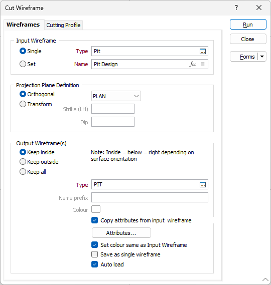
Projection Plane Definition
Specify an Orthogonal (LOOKING WEST, LOOKING NORTH, PLAN) or Transform projection plane. This setting will be used to define the direction in which the clipping string (or outline) will be stretched to create a surface that cuts the input wireframe.
If you select the Transform option, enter the Strike and Dip values that will be used to calculate the transformation. Strike and dip notation is inconsistent and must include the handedness of the measurement to make it unambiguous. In this case, the handeness of the strike is assumed to be left-handed. A left-handed strike is one where the structure slopes downwards to the left when viewed along the direction of strike.
Output Wireframe
Select one of the following Output options:
Keep inside
Select the Keep inside option to keep the wireframes that are situated inside the cutting surface:
- INSIDE = BELOW or RIGHT depending on the orientation of the surface.
Keep outside
Select the Keep outside option to keep the wireframes that are situated outside the cutting surface:
- OUTSIDE = ABOVE or LEFT depending on the orientation of the surface.
Enter (or double-click (F3) to select) the Type and Name of the wireframe solid that will be created as the output of the process.
Keep all
Select the Keep all option to keep all of the splits created as a result of the Cut operation. When this option is selected, each output wireframe is named and numbered automatically using a specified Name prefix.
Copy attributes from input wireframe
Select the check box to set the output wireframe attributes using the attributes from the input wireframe.
If the input wireframe is a set of wireframes with different types, the function copies wireframe attributes and their values from the first input wireframe.
When the check box is enabled, the Attributes dialog grid control is disabled, and only the attributes and data from the input wireframe will be appended to the output wireframes.
Attributes
Click the Attributes button to set Wireframe Attributes for the wireframe output.
User-defined attributes may be mapped against the fields in the Input file. It is also possible to specify a default value for each attribute. Default values are used when a corresponding value in the Input file is either missing or is not mapped.
Set colour same as input wireframe
Select this check box to apply the colour attribute of the Input wireframe to the Output wireframe.
Save as single wireframe
Select this option to save the Output wireframes as a single wireframe.
Auto load
Select this option to load the generated output in Vizex. The default draw style for an auto-loaded wireframe is 3D Shaded.
To slice a wireframe multiple times, using an orthogonal or transform cutting plane, or the sections defined in a section control file, select the Wireframe | Operations | Slice function.
Forms
Click the Forms button to select and open a saved form set, or if a form set has been loaded, save the current form set.