Geological Plane Rotations
![]()
The Geological Plane Rotations dialog is used to view or edit the parameters used to set the orientation of a geological plane that can be applied to your variograms.
The Geological Plane Rotations button on the Input Data tab of the Semi Variogram Map form is used to view or edit the parameters used to set the orientation of the map plane.
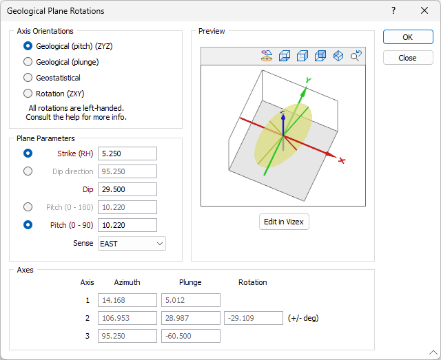
Axis Orientations
A choice of axis orientation modes is provided: for regular geological information such as strike, dip, and pitch, or for geostatistical model axes generated from semi variogram modelling.
Which axis orientation mode should I use?
The best axis orientation mode depends on the available data. This table summarises the requirements for each mode, which are described in more detail below:
|
Available data |
Best axis orientation mode |
|---|---|
|
Strike and dip of the orebody, pitch and sense of lineations within it. |
Geological (pitch) |
|
Strike and dip of the orebody, azimuth and plunge of lineations within it. |
Geological (plunge) |
|
Azimuth and plunge of three perpendicular axes, usually from directional semi-variogram modelling. |
Geostatistical |
|
Mathematical rotations around three perpendicular axes, often used by other applications. |
Rotation |
Take care when defining the axis orientations, especially in Geostatistical mode. For example, reversing Axis 1 (by changing the sign of its plunge and adding 180° to its azimuth) will have a corresponding effect on Axes 2 and 3.
Geological (pitch)
If you know the strike and dip of your data and have measured the pitch of lineations within it, you can use Geological (pitch) mode to create a matching
To set
- Set Axis Orientations to Geological (pitch).
- Enter the Strike and Dip of the data, and the Pitch and Sense of the lineations.
- The application will calculate the orientations of Axes 1 through 3.
Geological (plunge)
If you know the plunge and azimuth of lineations within your data, use Geological (plunge) mode.
To use Geological (plunge) mode:
- Set Axis Orientations to Geological (plunge).
- Enter the Strike and Dip of the data, and the Azimuth and Plunge of the lineations as Axis 1.
- The application will confirm that the Azimuth falls within the plane of the data, and then calculate the orientations of Axes 2 and 3. It will display a warning if the Azimuth is incorrect.
In Geological mode the main axis of the
Geostatistical
If you have modelled semi variograms and already know the azimuth of the first axis, and the plunge of the first and second axis, use Geostatistical mode to create a matching
- Set Axis Orientations to Geostatistical.
- Enter the Azimuth and Plunge of Axis 1, and the Plunge of Axis 2.
- The application will confirm that Axes 1 and 2 are perpendicular and then calculate the orientation of Axis 3. It will display a warning if the Axes 1 and 2 are not perpendicular.
Rotation
Rotation mode (the default mode) provides the simplest way to set
- Set Axis Orientations to Rotation.
- Enter the Azimuth and Plunge of Axis 1, and the Rotation of Axis 2.
- The application will then calculate the orientation of Axis 3.
The rotation terminology used above is equivalent to the following left-handed rotations, which are applied in the listed order:
• Axis 1 Azimuth = Z rotation (between -360 and +360)
• Axis 1 Plunge = X rotation (between -90 and +90)
• Axis 2 Rotation = Y rotation (between -90 and +90)
To visualise the handedness of these rotations, imagine grasping each axis with your left hand, with your thumb pointing along the positive direction. The direction in which your fingers curl indicates a positive rotation.
So, beginning with a rotation around the Z-Axis (what we would call an Azimuth rotation), grasping the axis with your left hand in a thumbs-up gesture (thumb pointing in the positive Z-direction), will result in your fingers curling around to the right. Thus, a positive rotation is to the right.
The same with a rotation around the X-Axis (what we would call a Plunge rotation); this time the thumb of your left hand points to the right and your fingers curl downwards and away from you.
The Y-Axis is trickier but works the same way. This time you hold your left hand as if you were stabbing something with a sword. Your thumb will point directly away from you and your fingers will curl downwards to your left.
Plane Parameters
If you have selected one of the Geological modes, enter the parameters that define the orientation of the plane. Strike and dip notation is inconsistent and must include the handedness of the measurement to make it unambiguous. In this case, the handeness of the strike is assumed to be right-handed. A right-handed strike is one where the structure slopes downwards to the right when viewed along the direction of strike.
For more information about Strike, Dip and Dip Direction, Plunge and Pitch, refer to the Orientation and Geometry topic.
Sense
For Geological (pitch) mode, select a Sense which indicates the general direction of the lineations. The application will automatically calculate the exact azimuth and plunge that constrains the lineations to lie within the plane. This information is displayed in the Axis 1 row of the Axes grid.
Whenever pitch is less than 90° there will be two possible azimuths; if the wrong Axis 1 azimuth appears in the Axes grid, choose a different sense.
Sense is disabled whenever one of the axial conventions (Geostatistical or Rotation) is used.
Axes
Axis 1 Factor
The length of the first or main ellipsoid axis, multiplied by the Radius to establish the final axis length. The Main Axis Factor is generally the longest dimension; in geological terms it represents the down-plunge length of the ellipsoid.
Axis 1 Azimuth
The azimuth (in degrees) of the long axis of the search ellipsoid measured clockwise from north, between 0 and 360. In geological terms, it represents the trend of linear features within a plunging orebody, such as fold axes or main structural lineations.
If you use either Geological orientation mode, the application will automatically calculate the Axis 1 azimuth. You must enter it for Geostatistical and Rotation modes. In Rotation mode and Geostatistical mode, the permissible range is between -360 and +360.
Axis 1 azimuth corresponds to strike whenever the Axis 1 plunge is zero (see below).
Axis 1 Plunge
The downward inclination of the main ellipsoid axis from horizontal (in degrees), between 0 and 90. Geologically, it represents the plunge of linear features within the orebody.
If you use Geological (pitch) orientation mode, the application will automatically calculate the Axis 1 plunge. You must enter it for all other modes. In Rotation mode and Geostatistical mode, the permissible range is between -90 and +90.
Axis 2 Factor
The length of the second ellipsoid axis, multiplied by the Radius to establish the final axis length. The Second Axis Factor usually falls between the Main Axis Factor and the Third Axis Factor; in geological terms it is similar to the down-dip length of the ellipsoid, but is measured in a plane perpendicular to Axis 1 instead of vertically.
Axis 2 Azimuth
The azimuth (in degrees) of the second ellipsoid axis measured clockwise from north, between 0 and 360. In Rotation mode and Geostatistical mode, the permissible range is between -360 and +360.
If you use Geostatistical orientations mode, you must enter the Axis 2 azimuth. The application will automatically calculate it for all other modes.
Axis 2 Plunge
The plunge of the second ellipsoid axis from horizontal, between 0 and 90°. In Geostatistical mode, the permissible range is between -90 and +90.
If you use Geostatistical orientations mode you must enter the Axis 2 plunge. The application will automatically calculate it for all other modes.
Axis 2 has no direct geological equivalent; however it equates to the down-dip direction of the plane containing the ellipsoid whenever the Axis 1 plunge is zero.
Axis 2 Rotation
If you use Rotation mode, specify the Axis 2 Rotation, measured in degrees from -90 to 90, in a plane perpendicular to Axis 1. The sign represents the orientation relative to Axis 1: when looking in the direction of Axis 1, a positive value represents an anti-clockwise rotation and a negative value a clockwise rotation.
Axis 2 rotation is equivalent to dip whenever the Axis 1 plunge is zero, although it can be either positive or negative. Rotation does not equate to dip if the Axis 1 plunge is anything other than zero.
Axis 3 Factor
The length of the third axis of the search ellipsoid, always perpendicular to the first and second axes. This value is multiplied by the Radius to establish the final axis length. The Third Axis Factor is usually the shortest dimension; in geological terms it represents the thickness of the search ellipsoid.
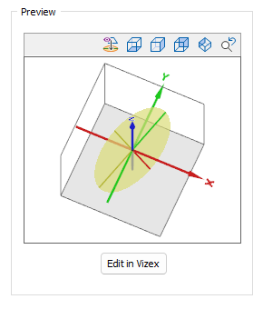
Preview
The settings in the Geological Plane Rotations window can be rotated and panned in a Preview window.
The preview can be rotated and panned interactively, or you can use the View buttons in the toolbar above the display to change perspective or align to the plane view as follows:
|
|
Align the plane view with major and semi-major axes. |
|
|
View from above (T) |
|
|
View from the West (L) |
|
|
View from the South (Shift + L) |
|
|
View from South East Isometric position |
 |
Move to the previous view |
If you click the Edit in Vizex button, the Geological Plane Rotations form collapses and you can change the details for the rotation in Vizex. Press Esc to return to the form.
OK
Click OK to set the orientation of the map plane and return to the Semi Variogram Map form. The rotation of your variograms will be updated accordingly.