Chart | Semi Variograms
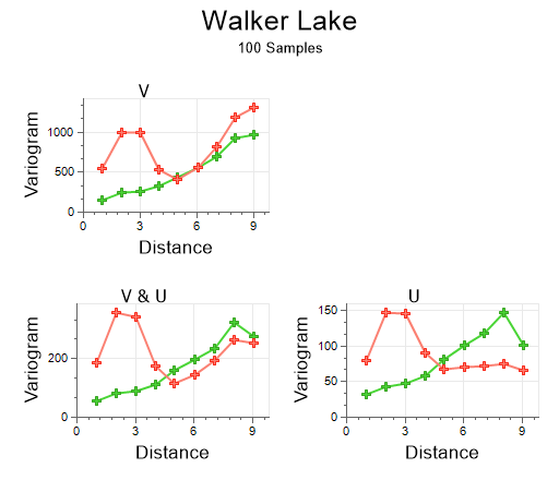
The Semi variogram chart will show a plot of the semi variogram values for each interval and for each direction. The X range is determined by the product of the interval and number of intervals, plus one at each end. The Y range depends on the maximum  (the analysis field) calculated from the data. The Y origin is 0.
 is half the mean squared difference between the sample values.
When you generate a chart, many of the tools and options on the Chart ribbon are common to most charts. See: Chart Tools
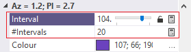
When the Variogram chart is open in Three Axes Model mode, you can set a different maximum lag distance (Interval multiplied by #Intervals) for each variogram using an interactive slider in the Properties window. Decimal interval values are supported. The slider can be prevented from scrolling using the Lock icon.
The Multiple Charts view option is the default and shows all the charts in one window. Select Single Chart to show each variogram individually.
Model Fitting
The model fitting workflow is fully interactive. The Chart Controls pane provides interactive tools for adjusting the model. This pane is resizable horizontally, so the grid can be enlarged and the cells made wider.
Each model component has a set of handles attached to it in the graph; just reposition each one as needed. The partial sill of the component immediately after the one you are adjusting will automatically absorb any sill adjustments, keeping the total sill constant and making it very easy to refine the model. Holding the Shift key temporarily disables this compensation. Mouse wheel shortcuts make it easy to zoom into any part of the model.
The option to lock component sills across multiple axes (directions) is provided.
A 3D Ellipsoid allows the theoretical variogram model to be inspected so that the directions of the axis and the relative anisotropy make sense with regard to the geology of the deposit.
On the Chart | Semi Variograms tab, in the Variograms group:
- Click Show Variance to toggle whether the variance line is visible or not.
![]()
- Click Show Pair Labels to toggle the display of per point pair count labels.
![]()
- Click Point Pair Scaling to toggle the scaling of points based on their point count.
![]()
-
Click Show Additional Directions to toggle the display of additional directions, including downhole:

Additional directions are written as parameters to the Variogram Control File, from where they can be re-loaded.
-
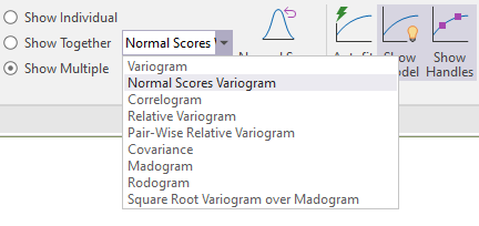
Use the radio buttons to show the variograms in one of 3 ways:
-
Individually: Display all the variograms individually. Use the Next and Previous buttons to cycle through them:


-
Together: Display all the variograms together on the same chart
-
Multiple: Display all the variograms on multiple charts
-
Select a Variogram type to recalculate the variograms without going back to the form:
-
When Normal Scores Variogram is selected as the Variogram type, fit the variograms in Normal Scores mode (by selecting Autofit Model). You can then click Normal Scores Backtransformation to backtransform to the original data:

- Click Autofit Model to automate the initial estimate of the nugget, ranges and partial sills. See: Semi Variogram Model Autofit
![]()
- Click Show Variogram Model to toggle the display of the semi variogram model and the Chart Controls pane.
![]()
- Click Show Handles to toggle the display of the (nugget, slope, etc.) handles on or off. These handles can be dragged in order to fit the model, but may sometimes obscure parts of the chart display.
![]()
- Click Fit View to Model to fit the view to show the entire model. The view will reset if the direction is changed, the experimental series is changed, or when the chart is refreshed.
![]()
-
Click Normalised Mode to toggle normalisation on and off.

Select Setup from the drop-down menu to select a different Normalisation mode:

- Click Measure Distance to measure the model using one of two modes. See: Measure Model Distance
![]()
- Click Clear Measure Distance to clear the measured search radii.
![]()
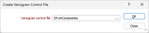
- Click Show Control File button to open and view a Variogram Control File. See: Show Control File
![]()
- Click Save Control File button to save you settings to a file (one direction must be defined for 2D, and three directions must be defined for 3D).
![]()
If you select an existing file, you will be prompted to overwrite or cancel.
To view the contents of the file you have created or selected, right-click in the Variogram control file response.
-
Click Properties to show or hide the Properties pane of the chart.

-
Click Chart Control to show or hide the Chart Control pane.
