Lithologies
The Lithologies grid on the Lithology tab of the
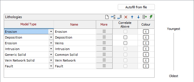
The Autofill from file button opens the Lithology form for entering string and/or structural data file details. These details must include a lithology field, and optionally Dip and dip direction Orientation details.
Strings
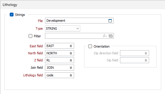
Select the Strings check box to specify the String file to use for the Surface Map lithology.
If not automatically specified, select the East, North and Z fields along with the required Lithology field. Optionally, you can specify a Join field.
If you select the Orientation check box, the Dip direction and Dip fields for the string can be specified.
Structural Data
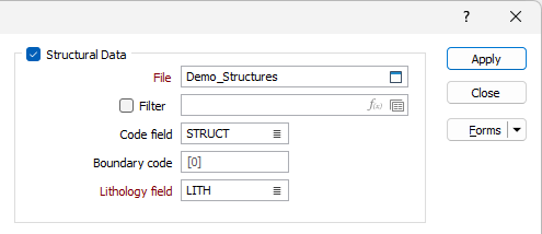
If you want to specify a Structural Data file for the surface map lithology, select the check box and use the File field to select the relevant structural data.
Optionally, you can apply a Filter and/or specify a Code field and a Boundary code.
A Lithology field must be specified for the structural data file.
Colour Coding
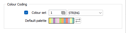
The Default palette will apply to the Surface Map lithology, unless you select the Colour set check box and specify a colour set to use. You can also use the drop down to select whether the colour set applies to the String or Structural data details where both exist.
Autofill the Grid
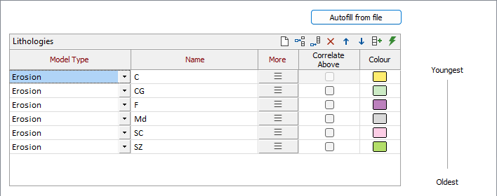
When the details have been entered, the Lithologies grid and Autofill the grid button are enabled.
![]()
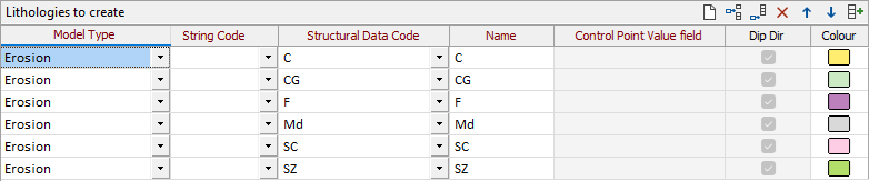
Click the Autofill the grid button to populate the Lithologies grid from the information configured in the Lithology form. A row will be added for every unique lithology value for the specified String/Structural data files. If the two files have matching lithology values (Note: these are case-insensitive), the row will contain both.
The Control Point Value field is enabled for rows where the model type requires that field.
The Dip Dir check box column allows you to disable (string file) orientation on a per row basis (if you have enabled that for the string file).
Colours will be applied from the default palette unless the lithology value matches names in a colour set (if specified). The colour set will reference the Lithology field in the string or structural data file, according to the selection made from the drop down.
If you change the Model Type for a Lithology in the grid, data for the lithology will be cleared unless you change to a model type within either of the following groups:
-
Erosion, Deposition, Vein, Intrusion, Fault
-
Generic Solid, Vein Network Solid
For example, if you change a Model Type from Erosion to Intrusion, data for the shared fields of that lithology will be retained. Conversely, if you change the Model Type from Erosion to Generic Solid, all data will be cleared, as there is no mapping between fields for these groups.
When the Lithologies grid has been configured as required, click Apply to populate the Lithologies grid in the Lithology tab of the Surface Map form.
If data exists in the Lithologies grid, you will be prompted to Overwrite or Append the populated rows:
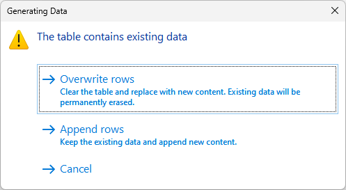
You can select Cancel if you do not want to apply the new data.
If you select Overwrite/Append from the prompt, rows configured in the Lithology dialog will be added to the Lithologies grid in the Surface Map form.
|
|
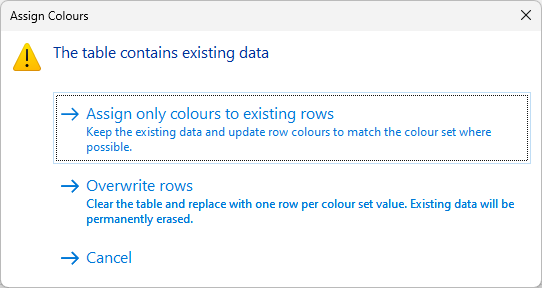
The Name from Colour Set button in the grid list toolbar is used to automatically populate the name field in the grid based on a selected colour set. If a colour set was selected in the Input options, clicking the Name from Colour Set button will populate the grid based on the set selected. If no Colour Set is defined in Input, you can click the Name from Colour Set button to open the Select Colour Set form. The colour set you select will also be entered in the Colour Set field of the Input options. When rows have been generated and changes have been made, and you need to change the colour set / palette, a confirmation prompt will be displayed on saving:
You can choose to keep the existing data and update the row colours to the new set / palette, or overwrite the rows in the table. Alternatively, click Cancel to discard the changes. |
|
|
The Auto Create Form Sets button in the grid automatically creates and names form sets based on the information already in the grid. If you click this button, the Form column of the grid will be populated. This will also populate the details in the form for you such as included lithology if the application finds a match between the unit in the Name cell and the list of lithology codes.
|

Use the buttons on the grid list toolbar to Manage the rows in the list.
Model Type
Select a Model Type for each of the lithologies included in the surface map:
|
Type |
Description |
|---|---|
| Erosion | A contact which will erode the unit below if applicable (e.g. intrusion). |
| Deposition | A contact which will deposit on top of the unit below and preserve any structures if applicable. Interpolation parameters are largely the same as for Erosion. |
| Vein | A wireframe solid which features a hanging wall and a foot wall. |
| Intrusion | A wireframe solid which is more irregular in nature. |
| Generic Solid/Vein Network Solid | An existing wireframe solid with associated Lithology codes that can be selected to represent the solid/ |
| A series of vein solids in geological order. Vein network solids will use all vein lithology codes written to the wireframe to represent the solid. | |
| Fault | A generated or defined wireframe surface representing a fault structure. |
Name
The names generated or entered for each of the lithologies. (See "Name from Colour Set" above).
Model Form
Double click or click the Forms icon to select a Lithology Modelling form set that corresponds to the model type of the lithology. Alternatively, right click in the cell and select New to create a new form set.
For information on the Model Forms for each model type, see:
Correlated Above
Enable these check boxes to force the roof (or floor if “Input strings define Erosion / Deposition” is set to “Bottom”) of an Erosion/Deposition lithology model to approximately mirror the roof (or floor) of the adjacent younger Erosion/Deposition lithology model. This option is only available for Erosion and Deposition model types and is not applicable to the youngest Erosion/Deposition, as the roof of that unit would represent the topography.
Colour
Use the Colour box in the cell to select a colour to represent the lithology on the row.
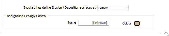
Input strings define Erosion / Deposition...
Use the drop down to select whether the input strings for the surface map define the roof (Top) or floor (Bottom) of Erosion and Deposition lithology models.
Background Geology Control
Name
Enter a Name for the Background Geology Control or leave the default. If there are any void spaces in your modelled area, a solid will be created and named using the value entered.
Colour
Double click the Colour icon to select a default colour for any solid created for the background geology control.