Vein Intercepts
![]()
Veins are commonly modelled with channel samples. However, channels do not always cross all the mineralisation in the vein. Modelling HW and FW for all contacts will result in inaccurate models. In these situations, the Vein Intercepts Edit tool can be used to select the intervals to model from each drillhole. The tool can be used to exclude segments and select whether to include HW/FW values, or only one or the other. The result is a better guide for the intercepts to be modelled.
The Intercept File option on the Vein form specifies the intercept file for the vein model. The vein modeller will output its automatically determined FW/HW contacts and orientations to this file and use the “USER_*” fields as input to the modelling process. If this file does not exist it will be created. If it does exist then the contents of the file will be used to modify the information provided in the interval file.
There are two records in the vein intercept file for each contact interval, one record representing the sub-interval from the starting depth to the mid-depth, and the second record representing the sub-interval from the mid-depth to the ending depth. User-specified intercept type and orientations can be defined via the USER_VALUE, USER_POLARITY, USER_DIP and USER_DIP_DIR fields in the vein intercept file.
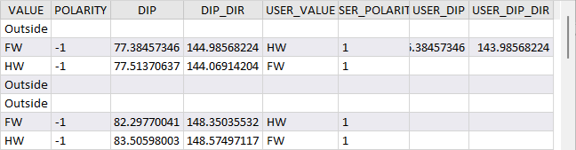
The USER_VALUE field for each sub-interval can be set to FW, HW or Ignore. If set to HW, then USER_POLARITY should be set to 1 if the contact is at the start of the interval or -1 if it is at the end. If the value is FW, then USER_POLARITY should be set to 1 if the contact is at the end of the interval, or -1 if it is at the start. Where the USER_VALUE for both sub-intervals is set to FW or HW, the polarity rule still applies, and opposite USER_POLARITY values will result. If the setting is Ignore, denoting waste intervals, that contact will not be considered for the model.
These vales can be updated using the Tools in the Vein Intercepts ribbon with a vein intercept model open.
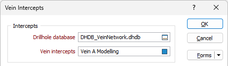
Intercepts
-
Double-click (or click on the Select icon) to select a Drillhole Database for the vein intercepts.
-
Click the folder icon to select a Vein Intercepts file, or press F5 to create a new one using the New File form.
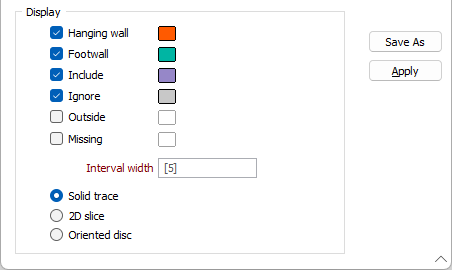
Display
-
Select the check box for any and all of the elements to be displayed in the vein model for the intercepts.
-
Use the colour box to select a colour for the displayed element.
-
Enter an Interval width for the vein intercept in the field provided.
By default, the vein intercept display mode is Solid trace. You can select a display mode from the options provided: Solid trace, 2D Slice or Oriented disc. If Oriented disc is selected, ticks will automatically be displayed.
When the required parameters have been entered in the Vein Intercepts form,
-
Click OK to generate the Vein Intercepts model.
The vein intercepts will be displayed in Vizex and the Vein Intercepts ribbon will be opened.
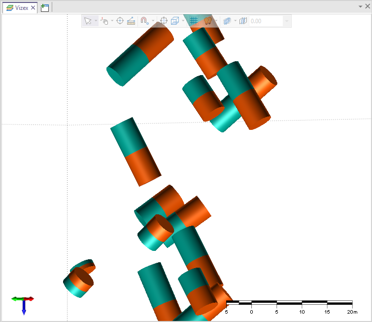
You can use the Tools on the Vein Intercepts ribbon to select, display and edit the vein intercepts model.