Fault
![]()
The Generate Fault function should only be used with a small amount of points (< 1000).
Input
File
Double click (or click on the Select icon) to select an Input file. Typically, the Input file will be a String or a Data file that defines the faults to be modelled. Other file types are also supported; including Survey, Structure and Report.
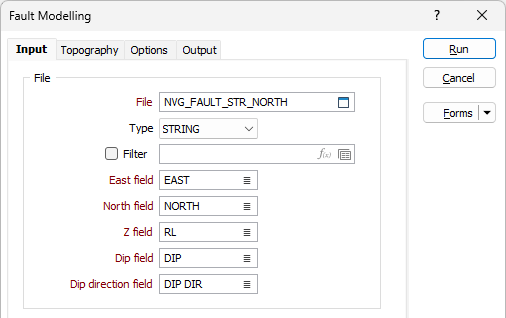
East, North and Z fields
Specify the names of the fields in which Easting, Northing, and Z coordinates are stored in the points file.
Dip and Dip Direction fields
The orientation of the generated wireframe is dependent on the Dip and Dip Direction of the points or strings in the Input file. Specify the fields in the Input file which contain a dip and a dip direction for each point.
The dip values in the Input file should be 0-90. Dip direction values should be 0-360. Any values outside of these ranges (i.e. negative dips) are ignored and a warning message is displayed after processing is complete.
Extra Control Points
When building the output wireframe, if the faults have been traced on a geological, geophysical or structural map, this data can be loaded from a supported file to provide extra control points.
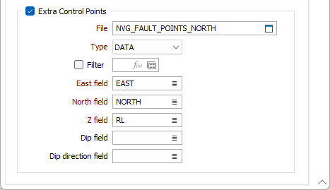
File
Double click (or click on the Select icon) to select a file that contains the control points that will be used to refine the model.
East, North and Z fields
Specify the names of the fields in which X, Y, and Z coordinates of the control points are stored.
Dip and Dip Direction fields
Optionally, specify the fields that contain a dip and a dip direction for each point.
Note: To better utilise processor resources across multiple applications and tasks, when running computer-intensive operations it may be necessary to reduce the number of cores used by the application.
To modify the number of cores the application can use:
-
Click the Project tab to open the backstage menu.
- Click on the Resources tab of the Options | System | System Options form.
Forms
Click the Forms button to select and open a saved form set, or if a form set has been loaded, save the current form set.
Run
Click Run to run the function.