Options
On the Options tab of the Fault Modelling form, you can choose an interpolation method, set the resolution of the generated wireframe and set extents to define the surface area for the interpolation.
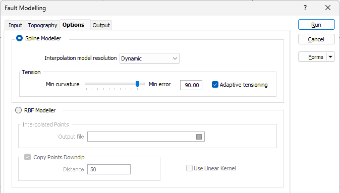
Spline Modeller
The Spline Modeller provides the smoothest output while closely honouring any Dip and Dip Direction data. It is ideal for producing surfaces that do not bend or change direction too quickly. If the input data defines a surface with abrupt changes or irregularities, the RBF modeller may be more suitable.
Interpolation Model resolution
Select a Dynamic, Standard, Fine or Superfine resolution for the output model. The option you select will determine the size of the blocks (grid spacing) for the area of interpolation.
Dynamic is the default option and will automatically adjust the resolution depending on the density of the data model, providing better than Superfine resolution in much less time.
Note that the Dynamic, Fine and Superfine interpolation resolution options may require a modelling parameter file to be stored in your Windows Temp directory and may take up to 1.5GB of space.
Tension
Use the slider to set a tension value between 0 and 100, where smaller values favour smoothness (minimum curvature) and larger values favour accurately honouring the contacts (minimum error). The default is 95.
When Dynamic is the selected resolution option, an Adaptive Tensioning check box option is enabled. Select this option when trying to model problematic data, for example, a surface which undulates very rapidly.
RBF Modeller
The RBF Modeller uses an RBF (Radial Basis Function) to interpolate a surface. The RBF method is a numerical technique that uses radial basis functions, which are mathematical functions that are centered at a certain point and decrease in value as you move away from that point. RBFs are used to approximate a function or a surface by combining multiple radial basis functions with different centres and weights. The RBF method is less sensitive to any Dip and Dip Direction data than the Spline Modeller, but it can better handle surfaces with abrupt changes or irregularities.
Interpolated Points
Enter (or click on the ellipsis button to select) the name of an Output file to which the interpolated points will be written.
Copy Points Downdip
Select this option to copy each point downdip by a specified Distance before creating the surface through those points. This may be necessary to make the fault dip correctly.
Use Linear Kernel
Two different RBF methods are available; Thin Plate Spline and Linear. The Thin Plate Spline method is the default and behaves in-between the Spline Modeller and the Linear RBF method. The Linear method can be used to model surfaces that change direction abruptly. It will produce surfaces that are less smooth than the Thin Plate Spline method, but it can deal with ‘rougher’ surfaces.
Extents
Define the area of interpolation:
East, North and Z fields
Specify the Minimum and Maximum extents of the surface in the East, North and Z directions.
Use the buttons on the local toolbar to Manage the rows in the list.
Click the Autofill Extents button to select the source of the extents you want to autofill.
The Minimum and Maximum extents of the generated wireframe can be extended beyond the limits of the input data if necessary. If extra control points are included (see below) the extents of the model will be extended to encompass them.
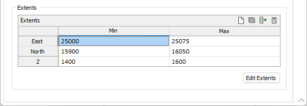
Edit Extents
Click the Edit Extents button to collapse the form and visually adjust the extents, automatically aligning the extents to a restriction rectangle in Vizex. Interactively adjusting the extents rectangle in the Vizex display, or in the Vizex Property Window, will update the values in the form.
See: Edit Extents