Wireframe and Direction
After defining an Surface or Solid from Profile and a Surface Restriction, use the inputs on the Wireframe and Direction tab to specify the distance and direction in which the output wireframe will be extruded.
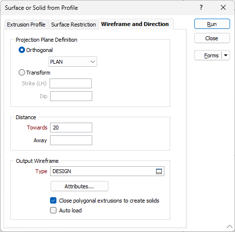
Projection Plane Definition
Specify an Orthogonal (LOOKING WEST, LOOKING NORTH, PLAN) or Transform projection plane that will be used to define the direction in which the clipping string or outline will be stretched to create an open surface.
If you select the Transform option, enter the Strike and Dip values that will be used to calculate the transformation. Strike and dip notation is inconsistent and must include the handedness of the measurement to make it unambiguous. In this case, the handeness of the strike is assumed to be left-handed. A left-handed strike is one where the structure slopes downwards to the left when viewed along the direction of strike.
Distance
Specify a Towards or Away distance for the extrusion.
For the Transform options, the distances Towards and Away are in terms of the Normal. For the Orthogonal options, the distances Towards and Away are in terms of the coordinate values.
For example:
If the projection plane is “PLAN” and the distance (Towards) is 100, then the Z of the extrusion will be 100m higher.
If the projection plane is “PLAN” and the distance (Away) is 100, then the Z of the extrusion will be 100m lower.
If the projection plane is “LOOKING NORTH” and the distance (Towards) is 100, then the North coordinates of the extrusion will be 100m smaller.
If the projection plane is “LOOKING NORTH” and the distance (Away) is 100, then the North coordinates of the extrusion will be 100m greater.
Output Wireframe
Type
Select the type of the Output wireframe.
Attributes
Click the Attributes button to set Wireframe Attributes for the wireframe output.
User-defined attributes may be mapped against the fields in the Input file. It is also possible to specify a default value for each attribute. Default values are used when a corresponding value in the Input file is either missing or is not mapped.
Close polygonal extrusions to create solids
When extruding a closed polygon, select this option to close the ends of the extrusion. See: Closing the ends of an open solid or closed surface
Auto load
Select this option to load the generated output in Vizex. The default draw style for an auto-loaded wireframe is 3D Shaded.
Run
Finally, click the Run button to run the function.