Bedding Plane from Points
![]()
Input
In the Bedding Plane From Points form, select the file type and double-click to select the file containing the points you want to use in the process. If required, define a filter to selectively control the records to be processed.
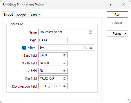
East, North and Z fields
Specify the names of the fields in which Easting, Northing, and Z coordinates are stored in the points file.
Dip and Dip Direction Fields
Unlike the New Plane From Points function (on the Grid / DTM tab, in the DTM Tools group), only one point is available to define the centre and rotation of the plane and you must specify fields in the input file which contain a dip and a dip direction for each point.
The dip values in the input file should be 0-90. Dip direction values should be 0-360. Any values outside of these ranges (i.e. negative dips) are ignored and a warning message is displayed after processing is complete.
Name and Code Fields
To assign Name and Code attributes to the generated wireframes, double-click (F3) to select the fields in the Input file that contain the values you want to assign. You cannot select a Code field unless a Name field has first been specified.
The Name and Code fields can be used to assign a colour set to the wireframes. For example, when generating wireframes from drillhole structural readings, the wireframes can be assigned the codes associated with each structural feature. This eliminates the need to perform multiple runs in order to generate and display the features in different colours.
Forms
Click the Forms button to select and open a saved form set, or if a form set has been loaded, save the current form set.
Run
Click Run to run the function.