Volume (Cut and Fill)
![]()
When calculating the volume between two DTMs, an estimate of the calculation accuracy is calculated, and a boundary file can be used to limit the calculation area. See: Volume Calculations
When calculating cut and fill volumes, Wireframe Boolean and Cut tools can be used, prior to the calculation, to restrict the calculation to a specific area. Cut and fill calculations can be applied to the design of open pits and stockpiles.
Note: If the process fails, this may be due to minor inconsistencies in the data. To pre-process the data prior to the calculatiion, perform a Wireframe Clean and/or a Wireframe Snap to ensure that both surfaces are valid.
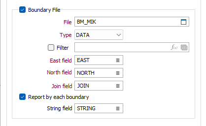
Input
Reference (Original) Surface
Specify the type and name of the Reference (Original) Surface DTM. To obtain the best performance and accuracy when calculating a volume between 2 DTMs, select the more complex of the two surfaces here.
Target (Final) Surface
Specify the type and name of a Target Surface DTM. This surface will be used with the Reference (Original) Surface to determine the cut and fill volumes.
The DTMs used by the Volumes function are created using either the New DTM option, or the Interactive New DTM option, on the Grid / DTM tab, in the DTM Create group. These two surfaces will be used to determine the cut and fill volumes.
Target (Final) Elevation
Specify an elevation. This elevation value will be used with the Reference (Original) Surface to determine the cut and fill volumes.
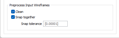
Boundary file
(Optional) Check the Boundary File option to select a File to limit the calculation area by defining a Polygonal Restriction.
Select the Report by each boundary option to report the calculation by each boundary separately. If you enter a value in the String field, the String field will be used to name each boundary. If any String fields are blank, a default name value of Boundary %d will be used.
Preprocess Input Wireframes
Cleaning or snapping the wireframes may reduce memory usage when large datasets are processed.
Clean
Select this check box to clean the input wireframes.
Snap together
Select this check box to snap the wireframes to a default (or specified) tolerance.
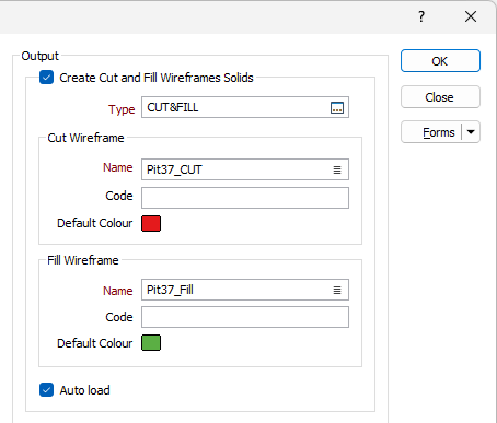
Output
Create Cut and Fill Wireframe Solids
Select the check box to save the Cut and Fill volumes as wireframe solids. The generated solids are of the same wireframe type, and are given a different name, code and default colour.
- Fill (green)
- No change (blue)
- Cut (red))
If necessary, you can double-click on the colour icons to change the default colours prior to running the calculation:
Autoload
Select this option to load the generated output in Vizex. The default draw style for an auto-loaded wireframe is 3D Shaded.
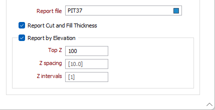
Report file
Enter the name of the Report file. This will contain the area and volume estimates, including the volume between elevations, if you are reporting by elevation.
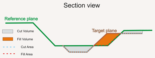
The volume above the reference surface (fill) and below the target surface (cut) are also calculated and reported. The fill area, the cut area, and the area of each surface, are written to the Report file.
The REFERENCE WIREFRAME NAME and the TARGET WIREFRAME NAME are the wireframes or the DTM planes between which the volume is to be determined.
Usually, the reference surface is the bottom plane and the target surface is the top plane, but this is not necessarily the case.
The REFERENCE WIREFRAME AREA and the TARGET WIREFRAME AREA are the areas of the specified wireframes measured in square meters.
The FILL VOLUME is the volume above the reference wireframe and below the target wireframe, only for the area which is common to both wireframes (in plan view).
The CUT VOLUME is the volume below the reference wireframe and above the target wireframe, only for the area which is common to both wireframes (in plan view).
The FILL AREA is the area of the common plane created by superimposing the two specified wireframes, on the condition that this common plane lies above the reference wireframe and below the target wireframe.
The CUT AREA is the area of the common plane created by superimposing the two specified wireframes, on the condition that this common plane lies below the reference wireframe and above the target wireframe.
Report Cut and Fill Thickness
Select the check box to calculate the thickness of one or more benches, or depth ranges, either between two triangulated surfaces, or between one triangulated surface and a target elevation.
Report by Elevation
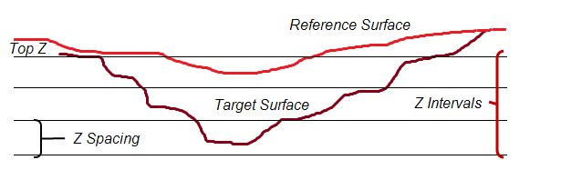
Select the check box to calculate the volume of one or more benches, or depth ranges, either between two triangulated surfaces, or between one triangulated surface and a target elevation.
Specify the volumes to be calculated from a Top Z elevation, at a given Z spacing, and for a given number of Z intervals.
Forms
Click the Forms button to select and open a saved form set, or if a form set has been loaded, save the current form set.
Run
Finally, click the Run button to run the function.