Output
On the Output tab of the DTM Thickness form, you can generate a Thickness DTM and a Thickness Points file.
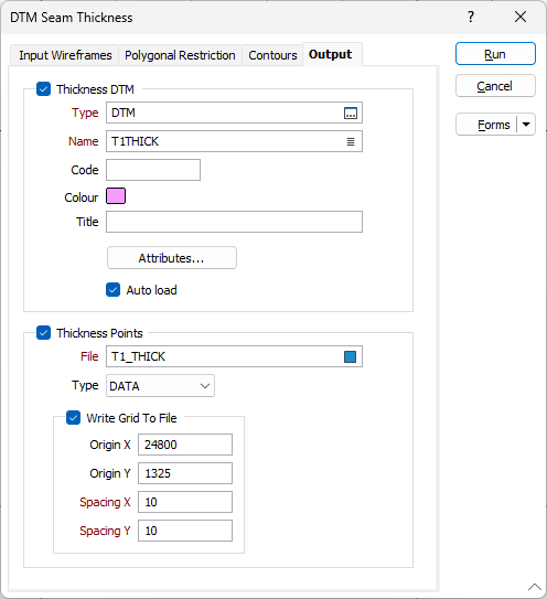
Thickness DTM
(Optional) Enter a Name and a Type for the Thickness DTM. This file uses the points in the existing Roof and Floor DTM’s. The Z value in the new DTM file is the calculated thickness at each of these points.
Click the Attributes button to specify wireframe attributes. Attributes are characteristics of the feature that a wireframe represents. There are two types of wireframe attributes: Standard and User-defined.
Thickness Points
Enter a name for the Thickness output file. This file will contain the coordinates, and calculated seam thickness at each point in the Roof and Floor DTM files and at the grid nodes (if Write grid to file is selected).
If the Write grid to file option is selected (See above) then the output file will contain a set of regularly spaced points. Otherwise the points will be the vertices of the Roof and Floor DTMs.
For each point, the thickness between the Roof and Floor DTM is calculated and written to the output file.
Write Grid to File
By default, the points in the Thickness output file are the vertices of the Roof and Floor DTMs. To write a set of regularly spaced points to the output file instead, select the Write grid to file option.
Enter the Origin X and Y and the Grid Spacing X and Y. Setting the X origin to 0 and the X spacing to 10 will define nodes at 0, 10, 20 etc. If the X origin was 5, the nodes would be 5, 15, 25 etc.
The points written to the Thickness output file will be the grid nodes that are inside the DTM boundary.