Distance to Drillhole

For mineral exploration and the planning of drillhole locations, it is useful to assess the distance between a location existing drillholes. This can often be achieved using either a block model, by colouring a wireframe by a distance attribute, or by creating buffer wireframes around drillholes.
The Distance to Drillhole tool provides a simpler solution by allowing users to select an input drillhole database and select from several different output options to assess the distance to drillholes.
Input Drillhole Database
Specify the following parameters in the Input group:
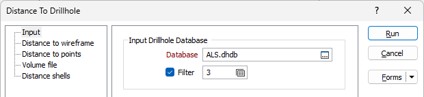
Database
Double-click (F3) to select the name of the database containing your data. Optionally, apply a filter to limit what data is displayed. See: Filter.
Outputs
The following options can be selected in the Outputs group:
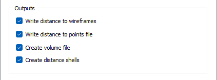
Write distance to wireframes
Select this option to write, to the Input database, the calculated distance between the drillholes and the surfaces and/or solids to an attribute in a nominated wireframe or wireframe set.
With this option selected, the Distance to wireframe tab is enabled and you can specify the wireframe / set and attribute to write the distances to. Distance to drillhole is calculated from the wireframe vertices and written as point attributes.
See Distance to Wireframe to configure the details.
Write distance to points file
Select this option to write the distance information to a specified attribute in a points file. With this option selected, the Distance to points tab is enabled and you can specify the points file and the related direction and distance fields. Distance to drillhole is calculated by the points in the file.
Writing the distance information to the points file allows the display to be coloured by distance. See Distance to Points to configure the details.
Create volume file
Select this option to output distance within a volume file. Selecting the option will enable the Volume file tab, which is used to configure the Extents and Output parameters for the Volume file. When auto-loading a volume file, an Isosurface value can be entered to display shells in the volume file.
See: Volume File to configure the details.
Create distance shells
Select the Create distance shells option to generate wireframes for each drillhole, at the distance(s) specified in the grid.
With this option selected, the Distance shells tab is enabled and you can set the Distance shells and the Wireframe output options. Wireframes can be Distance shells (overlapping) or Distance intervals (non-overlapping) when there are multiple distances specified. You can also output a wireframe per hole or a wireframe merged by distance, as well as specify rounded or flat ends.
See Distance Shells to configure the details.
Trim to Topography
The Trim to Topography options provide a way to generate a surface (e.g. topography) to which the Volume file and/or Distance shell outputs will be limited. This option is only available when the Create volume file and/or Create distance shells option is selected. When configured, the Trim to Topography details are applied to the created output file as well as any requisite volume file and distance shells.
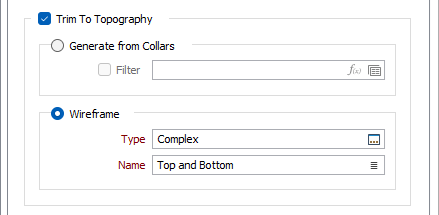
Generate from Collars
Select the Generate from Collars option to generate topography from the collar data in the drillhole database.
You can select the Filter check box and select a filter to determine the records in the drillhole database that will be processed for collar information, if required.
Wireframe
Select the Wireframe option to choose a wireframe surface that represents the topography. Select the Type of the wireframe and the Name of a wireframe of that type.
Restrict to Wireframes
Select the Restrict to Wireframes option to limit the Volume file and/or Distance shell outputs to a specified wireframe or set of wireframes. The configured wireframe/s will be used to create buffers around drillholes at a specified distance/s.
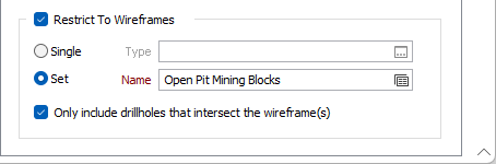
Single
Select the Single option to specify a single wireframe Type and Name to restrict the Volume file and/or Distance shell outputs.
Set
Select the Set option to specify the Name of a wireframe set with which to restrict the Volume file and/or Distance shell outputs.
Only include drillholes...
Select the Only include drillholes... option to use only holes that intersect one or more of the restrictive wireframes for distance measurements. The option applies to volume and shell outputs and is enabled by default.
Forms
Click the Forms button to select and open a saved form set, or if a form set has been loaded, save the current form set.
Run
When you have specified inputs and outputs, click Run to begin the process.