True Thickness
![]()
True thickness calculation determines the most accurate thickness value by determining the geological orientation for a plane using an event or interval file, or a wireframe. The function requires a Drillhole Database (DHDB) as one of its inputs to allow the following values to be directly accessed from the database:
- Azimuth and Dip
- Bedding Plane Dip, and Dip Direction (for an Event file associated with the database)
Input
Specify the following parameters in the Input group:
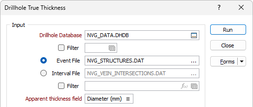
Database
Double-click (F3) to select the name of the database containing your data. Optionally, apply a filter to limit what data is displayed. See: Filter.
Event File
Double-click (F3) to select the name of an Event file associated with the chosen database. When an Event file is specified, the function uses the HOLE, DEPTH and APPARENT THICKNESS field values to calculate True Thickness. The Hole and Depth are used to interrogate the Drillhole Database to determine the Azimuth and Dip at that point.
If required, define a filter to selectively control which records in the file will be processed.
Interval File
Double-click (F3) to select the name of an Interval file associated with the chosen database. When an Interval file is specified, the function uses HOLE, (FROM + TO)/2 and (TO - FROM) values to calculate True Thickness.
If required, define a filter to selectively control which records in the file will be processed.
Apparent Thickness field
For an Event file, double-click (F3) to specify the name of the field containing drilled thickness values as measured along the drillhole.
Geological Orientation
The Geological Orientation details can be generated from the event or interval File or a Wireframe.
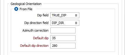
From File
Select the option to use the event or interval file for the calculation and specify the following defaults:
Dip Field
For an Event file, double-click (F3) to specify the field containing values which represent the Dip angle of formation.
Dip direction Field
For an Event file, double-click (F3) to specify the field containing values which represent the bearing of the formation Dip direction.
Azimuth correction
Optionally enter an Azimuth correction (+ or -) if you want to correct the values output to the Interval or Coordinate files.
Adjustments are made to all azimuth values used in the display without altering the actual values in the Collar and Survey files. There is no need to make adjustments if the result of the correction is negative or greater than 360 degrees.
Azimuth correction is useful when the survey azimuths are recorded in terms of true North with a known deviation from grid North.
Default Dip
Enter the dip angle of formation, measured from horizontal (0), through which true thickness is to be calculated. The Default Dip value must be positive (down) and in the range 0 - 90.
The Default value will be used when there is no value defined in the Dip field.
Default Dip Direction
Enter the default bearing of the Dip direction. This is at right-angles to the geological strike and is limited to a value in the positive range 0 - 360. The default value will be used when there is no value defined in the Dip Direction field.
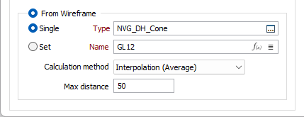
From Wireframe
To generate the true thickness calculation details using a wireframe, select the option and specify a wireframe Single or Set by Type and/or Name.
Use the Calculation method drop down list to select a method to use to calculate the true thickness from the wireframe/set.
-
Interpolation (average) - Calculates the local orientation by averaging the orientation of nearby wireframe surfaces.
-
Nearest point - Calculates the orientation using the orientation of the closest wireframe surface.
Max distance
Enter Max distance value in the field. Any intervals that are further than this distance from the wireframe closest point are written with blank true thickness values.
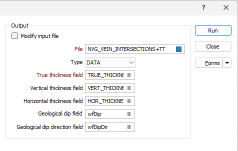
Output
Specify where the results of the calculation will be written in the Output group.
Modify Input file
Select this check box if you want to write the results of the calculation to the Input file rather than to a separate Output file.
If the Modify Input file check box option is selected, the following prompts will be disabled:
File
Select a file type and enter or double-click (F3) to select the name of an Output file.
When the Input file is an Event file, DEPTH values are written to the Output file. When the Input file is an Interval file, FROM and TO values are written to the Output file.
True thickness field
Double-click (or click on the List icon) to specify the name of the field in the Output file where the results of the True Thickness calculation will be written.
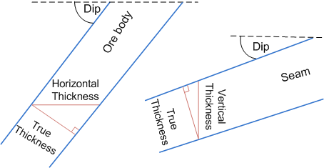
Vertical and Horizontal thickness fields
Depending on the orientation of an ore body, and the mining method, it is often a requirement to calculate the vertical or horizontal thickness of the ore body, in addition to true thickness.
Double-click (or click on the List icon) to specify the name of the fields in the Output file where Vertical thickness and Horizontal thickness values will be written.
Geological Dip field
Double-click (or click on the List icon) to specify the name of the field in the Output file where the Geological Dip value will be written. Geological dip is calculated from the wireframe.
Geological dip direction field
Double-click (or click on the List icon) to specify the name of the field in the Output file where the Geological Dip direction value will be written. Geological dip direction is calculated from the wireframe.
Forms
Click the Forms button to select and open a saved form set, or if a form set has been loaded, save the current form set.
Run
Click Run to run the calculation.