Floor (+Roof) to Solid
If you have the Surveying module, this option is also available on the Survey tab in the Underground Tools group.
![]()
The floor "surface" is generated by creating a DTM using the Floor Sidewall string as both the input data and the boundary.
The roof "surface" is generated by creating a DTM using the Roof points and the Roof Sidewall string as the input data and the Roof Sidewall string as the boundary.
A triangulation is generated between these two surfaces to create a solid.
Floor Sidewall
File
Select a file type and then double-click, or click on the Select icon, to select a file that contains the floor sidewall strings or points. If required, define a filter to selectively control the records to be processed.
Easting and Northing and Z fields
Specify the names of the fields in which Easting, Northing, and Z coordinates are stored in the input file.
Join field
In forms that require polylines as an input, the values in this field define whether the data points in the input file should be joined by a line. If successive records have the same value in this field, a line will join the points. If two-factor topology is required, the values in a String field may also be used to segment the lines.
String field
In most forms, the String field is an optional generic attribute used to store a secondary input such as a code. Traditionally, this field has also been used with the Join field to define whether data points should be joined by a line, or strung, hence the name.
Roof Points
File
Select a file type and double-click (F3) to select the file containingroof points. If required, define a filter to selectively control the records to be processed.
Easting and Northing and Z fields
Specify the names of the fields in which Easting, Northing, and Z coordinates are stored in the file.
Join field
In forms that require polylines as an input, the values in this field define whether the data points in the input file should be joined by a line. If successive records have the same value in this field, a line will join the points. If two-factor topology is required, the values in a String field may also be used to segment the lines.
String field
In most forms, the String field is an optional generic attribute used to store a secondary input such as a code. Traditionally, this field has also been used with the Join field to define whether data points should be joined by a line, or strung, hence the name.
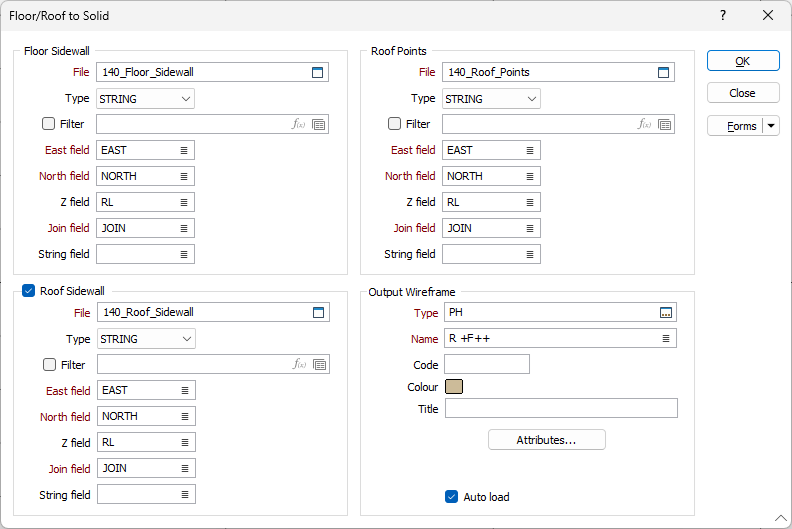
Roof Sidewall
Select this check box to generate a solid using roof sidewall strings or points, in addition to floor sidewall strings or points.
If there are no Roof Sidewall strings or points, the Floor sidewall strings or points are projected vertically.
File
Select a file type and then double-click, or click on the Select icon, to select a file that contains the floor sidewall strings or points. If required, define a filter to selectively control the records to be processed.
Easting and Northing and Z fields
Specify the names of the fields in which Easting, Northing, and Z coordinates are stored in the input file.
Join field
In forms that require polylines as an input, the values in this field define whether the data points in the input file should be joined by a line. If successive records have the same value in this field, a line will join the points. If two-factor topology is required, the values in a String field may also be used to segment the lines.
String field
In most forms, the String field is an optional generic attribute used to store a secondary input such as a code. Traditionally, this field has also been used with the Join field to define whether data points should be joined by a line, or strung, hence the name.
Output Wireframe
Type and Name
Specify the type and name of the generated wireframe.
Colour
Specify a default display colour for the generated wireframe.
Attributes
Click the Attributes button to set standard and user-defined attributes for the wireframe. When you save a wireframe, you should set standard attributes (colour and title settings etc.).
Auto load
Select this option to load the generated output in Vizex. The default draw style for an auto-loaded wireframe is 3D Shaded.
Forms
Click the Forms button to select and open a saved form set, or if a form set has been loaded, save the current form set.
Manage
To save the types, attributes and names you have defined and re-use them in other functions, select Manage button to create a form set or load an existing form set.
Save
Click Save to save your changes as the default form set.
Save As
Click Save As to save your changes as a new form set.
Reset
Click Reset to clear the form of all values and reset the form to its default state.
Run
Finally, click Run to run the process.