Tunnel to Centreline
If you have the Surveying module, this option is also available on the Survey tab in the Underground Tools group.
![]()
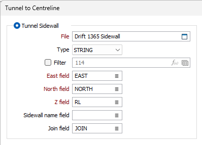
Tunnel Sidewall
Select this option to generate centrelines from tunnel sidewall strings.
File
Select a file type and double-click (F3) to select the file containing polygonal (sidewall) shapes. If required, define a filter to selectively control the records to be processed.
Easting and Northing and Z fields
Specify the names of the fields in which Easting, Northing, and (optionally) Z coordinates are stored in the Input file.
Sidewall name field
(Optional) Specify the name of the field containing sidewall names. These name strings define whether data points will be joined to define a sidewall polygon. The values of this field in successive records must be the same before the points will be strung.
Join field
(Optional) Specify the name of the field containing values which define whether data points will be joined by a line i.e. strung together to form a sidewall polygon. If successive records have the same value in this field and no Sidewall name field is defined a line will join the points. If a Sidewall name field is defined, then values in each field in successive records must be the same before the points will be strung.
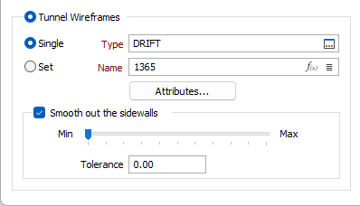
Tunnel Wireframes
Select this option to generate centrelines from closed tunnel wireframes. A common use case is where a planner is provided with as-blasted data, development wireframes for example, and needs to generate centreline strings for subsequent ring design or reconciliation tasks.
To process a single wireframe, select the Single option, select the Type of the wireframe, and then the Name of a wireframe of that type.
To process multiple wireframes, expressions, wildcards and partial names may be used in the Name field to select multiple wireframes as an adhoc wireframe set. A right-click Preview option will perform a check of an expression before using that expression to generate an updated list of wireframes. Alternatively, you can click the Expression icon ![]() and use the Expression Editor to create, modify and validate the expression. When a name or wildcard is entered in the Name field, and the Expression button is selected, the name/wildcard will automatically be converted to a valid expression when opened in the editor.
and use the Expression Editor to create, modify and validate the expression. When a name or wildcard is entered in the Name field, and the Expression button is selected, the name/wildcard will automatically be converted to a valid expression when opened in the editor.
To process the wireframes in a predefined wireframe set, select the Set option.
It is recommended that you Validate wireframes prior to using them in any process.
Attributes
Click the Attributes button to assign wireframe attributes to the output strings,
To aid in the identification of the outputs, the STRING field of the centrelines will also be populated with the names of the corresponding input tunnels.
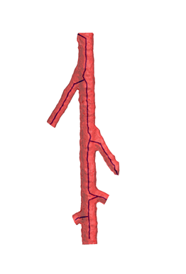
Note: this function is designed to process flat or slightly inclined tunnel solids such as typical production drives. The results may be unexpected when processing steeply inclined solids.
Wireframes with other tunnels branching out (such a the one in the below image) can be used as inputs, however additional post-processing may be required to remove unwanted artefacts that result from these branches.
Smooth out the sidewalls
When the input is one or more tunnel wireframes, the algorithm generates sidewalls that are subsequently processed to generate output centrelines.
Select this option and use the slider to simplify the sidewalls (reduce the number of data points) that are used to generate the centrelines. Alternatively, enter a value (between 0 and 100) in the Tolerance field.
The use of this option may result in cleaner outputs.
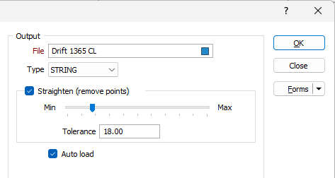
Output
File
Select an output file type and then enter (or double-click (F3) to select) the name of the output file.
Straighten (remove points)
Select this option to straighten the centreline by removing points. No straightening will occur when the slider is set to None. The more points you choose to remove (by moving the slider towards Many) the straighter the result will be.
Auto load
Select this check box to load the generated output in Vizex.
Forms
Click the Forms button to select and open a saved form set, or if a form set has been loaded, save the current form set.
Manage
To save the types, attributes and names you have defined and re-use them in other functions, select Manage button to create a form set or load an existing form set.
Save
Click Save to save your changes as the default form set.
Save As
Click Save As to save your changes as a new form set.
Reset
Click Reset to clear the form of all values and reset the form to its default state.
OK
Click the OK button to run the function and generate the solid.