Waste Dump Modeller
The Dump and the Stockpile are the mine locations used to store and accumulate waste rock (waste dump) and ore (stockpile) material. The main parameters of a dump or a stockpile are its volume (capacity) and the area of its base. The aim is to store as much rock as possible, in as small an area as possible. For more information, refer to the Waste Dump/Stockpile Volumes topic.
![]()
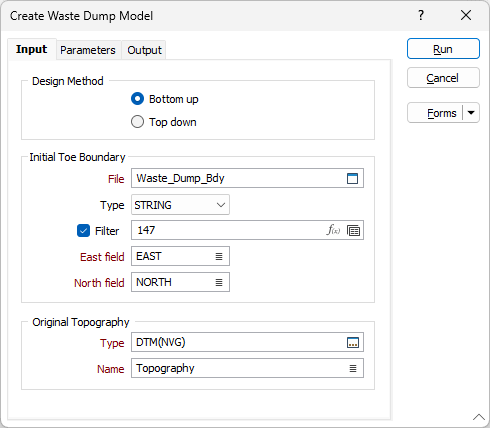
Design Method
You can choose to generate the terraces of the dump or stockpile in a Bottom up or Top down direction.
Bottom up
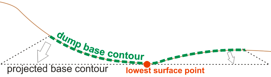
Select this option to project the dump toe string upwards using the specified parameters (slope angle, lift height and top elevation level). In this mode, the dump design process is carried out in three steps:
- The toe string is draped onto the topography, and the lowest point is found. Now the string is projected downwards (based on the slope angle) to that elevation.
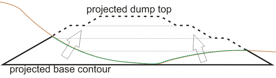
- The design of the dump starts from the projected base contour, upwards until it reaches the specified elevation level limit or the Target volume. The projected dump top contour should be at least equal to the highest point of the initial base contour. Therefore the process should check the elevation level limit and the dump height parameters and provide a warning if necessary.
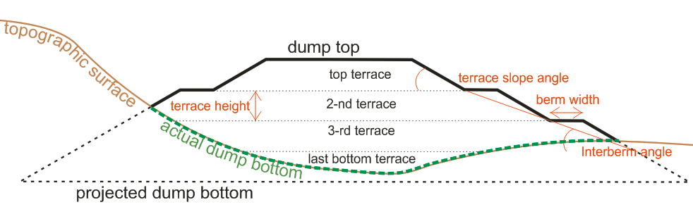
- Finally, the dump design is clipped by topographic surface.
Top Down
The input boundary string is assumed to be the crest of the dump. The string is projected down to the topographic surface, using the specified parameters (slope angle, top elevation level, lift height and berm width).
If the Top Down method is used and the Final Surface setting is based on a Z value, then the defined Z elevation is applied to the coordinates of the input boundary string, before the string is projected down from that elevation.
Initial Toe Boundary
Note that the content of the Input file is referred to as either “Toe Boundary” or "Final Surface Boundary” depending on whether the chosen Design Method is Bottom up or Top down.
File
Select a File Type (the default is String) and enter (or double-click (F3) to select) the name of the File that contains the toe or final surface boundary of the waste dump or stockpile.
The boundary should be a single closed polygon. If the file contains several polygons, a filter should be applied.
East and North fields
Specify the names of the fields in which Easting and Northing and coordinates are stored in the Input boundary file.
You do not need to specify a Z field. The toe boundary is draped onto the topography, and the Z of the final surface boundary is defined on the Parameters tab (or is calculated from the Target volume).
Original Topography
Type and Name
Enter (or double-click (F3) to select) the Type and Name of the topography surface that will be used as input to the process.
Forms
Click the Forms button to select and open a saved form set, or if a form set has been loaded, save the current form set.
Run
When you have set parameters and specified output options, click Run to generate the waste dump.