Event
On the Input tab of the Event form, select the input data for the events that will be shown downhole:
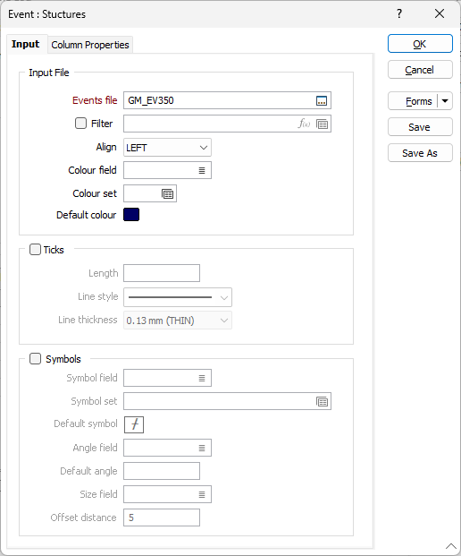
Input
Event File
Double-click (or click on the Select icon) to select the name of the file that contains the data you want to display. Select the Filter check box if you want to apply a filter to the file.
Enter a Filter Number in the adjacent box. Double click (F3) to see a list of existing filters. Right click (F4) to open the dialog box where you can create a new filter.
A filter can be useful when you want to apply a restriction on a field other than the one being displayed, for example, to show the assays in a particular zone, or show the assays for specific holes.
Ticks
Select this option to display ticks rather than symbols. The Offset distance and the Size factor you specify are applied to the symbols, or to the ticks (when this check box is selected).
Length
Specify a tick length
Line style
Select a line style. A preview of each style is shown in the drop-down list. A variety of solid, dotted, and dashed line styles are available for selection.
Line thickness
Use the drop-down menu to select a (THIN, MEDIUM, THICK or other) line thickness.
Symbols
Select this option to display symbols rather than ticks. The Offset distance and the Size factor you specify are applied to the symbols, or to the ticks (when this check box is selected).
Symbol field
Specify the name of
Symbol set
Double click (F3) to select the set that will be used to determine the symbol that will be displayed. The symbol set maps symbols to text strings or numeric ranges. This determines a symbol for each value in the chosen (mapped)
Default Symbol
Double-click in the Default Symbol box to select the symbol to be used when a Symbol
Double-click the Symbol icon to choose a symbol. You can source symbols from any TrueType or OpenType font.
Angle field
Enter the name of the field containing symbol angle values (0-360°). A value of 0 will display the symbol in its natural orientation. A value of 90 will display the symbol rotated 90° in the clockwise direction.
Default angle
Enter the default angle, in degrees, that will be applied to symbols at points where there is no entry in the symbol angle field.The default is 0°.
Size field
Enter the name of the field containing the factor that will be used to control the symbol size. The default is 1.
Offset distance (symbols)
Specify an offset distance (in grid units) that will be used to display the symbols.