Simplify
![]()
The distance from a vertex to the plane that results from the removal of the vertex is measured. This value cannot exceed the specified tolerance value.
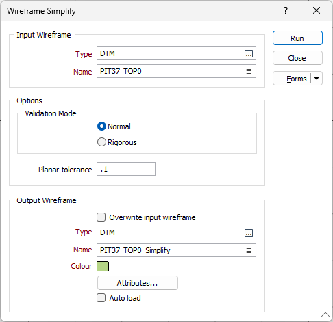
Input Wireframe
Select the type of the wireframe and then enter (or double-click to select) the name of the wireframe that will be used as input to the Simplify process. Wireframe types are defined in a triangulation database (*.tridb) file, and may be located in the current project or in any folder location.
Options
Validation Mode
Select the Normal radio button to apply the fast validation method to the simplify wireframe clean-up process.
Select the Rigorous radio button to apply the complete validation method to the clean-up process.
Planar Tolerance
Enter a value in grid units. This is the maximum amount that the triangulation is allowed to move in any direction after vertices are removed.
If no Planar tolerance is specified, a default value of 0.01 will be applied automatically.
Specifying a large Planar tolerance will significantly alter the nature of the triangulation.
Output Wireframe
Select the Overwrite input wireframe option if you want the result of the process to be applied to the Input wireframe/s.
If the Overwrite input wireframe option is selected for a wireframe Set, all input wireframes are overwritten with their cleaned counterparts. If the option is not selected, the output Name is disabled and new wireframes are created for the output Type with the same name as their inputs.
If the Overwrite input wireframe is not selected for a Single wireframe, a cleaned output wireframe will be created and the input wireframe will not be overwritten.
If the option is not selected for a Single wireframe and an ad hoc Set is specified, new wireframes are created in the output Type. Names for these are provided by the output Name field, followed by an underscore “_” and the name of the input wireframe from which they came.
Output
Type and Name
Specify the type and name of the Output wireframe.
Colour
Specify a default display colour for the Output wireframe.
Attributes
Click the Attributes button to set Wireframe Attributes for the wireframe output.
User-defined attributes may be mapped against the fields in the Input file. It is also possible to specify a default value for each attribute. Default values are used when a corresponding value in the Input file is either missing or is not mapped.
Auto load
Select this option to load the generated output in Vizex. The default draw style for an auto-loaded wireframe is 3D Shaded.
Forms
Click the Forms button to select and open a saved form set, or if a form set has been loaded, save the current form set.
By design, the Forms button is not available for loaded Vizex layers (i.e. when opening the form set properties of a layer in the Vizex Layer Display pane). In Vizex, the Forms button is only available for new forms opened via the Home tab or the Vizex tab, in the Layer group (or by double-clicking on a form type node in the Vizex Layer Types pane).
Save and Save As
Click the Save button to save the changes you have made to the form set. Click Save As to save your changes as a new form set. Save As will default to the first available form set number.
Reset
Click Reset to clear the form of all values and reset the form to its default state.
Reset Tab
For tabbed forms, select Reset Tab to clear the active tab of all values and reset the tab to its default state - without making any changes to other tabs in the dialog.
Undo and Redo
Click Undo (CTRL + Z) to undo recent changes in the form. After an Undo, click Redo (CTRL + Y) to restore the last change that was undone.
Collapse
Collapse (roll-up) the form to preview a chart, or preview the results of an operation in Vizex, or obtain input values from Vizex, the Property Window, the File Editor, or the Plot Editor.
Run
Finally, click Run to begin the process.