Block Model Outer Shell
![]()
When you run the function, a series of wireframes that represent the outer shell of the block model are created. (To generate a series of shells within an ore body, select Wireframe | Block Model Grade Shells.)
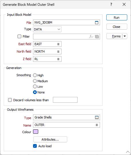
Input Block Model
File
Double-click (or click on the Select icon) to select the name of the input block model file.
East, North and Z fields
Double-click (or click on the Select icon) to select the names of the coordinate fields in the input file.
Generation
Smoothing
You can create more realistic solids by choosing a (High, Medium, or Low) smoothing option. To turn smoothing off, choose None.
If smoothing shows no visible result, this may be due to the fact that the parent block size is too big, possibly because the block model has no regular structure, or because the average cutoff of the parent block is too low
The Smoothing process requires a model that has a regular structure in all three dimensions. An error will be reported if the input model is a Seam Block Model (SBM) file.
Bear in mind also that block models from third-party applications such as Surpac, may have vastly different block sizes and this may lead to a big parent block size. Such models will need to be reblocked, either at the time they are imported or using Block Model | Reblock Model | Reblock.
Discard volumes less than
If this option is selected, all independent triangle shells with a volume less than the specified minimum volume will be removed.
Any value less than or equal to zero will disable volume removal.
Output Wireframes
Type and Name
Select an Output Wireframe Type and enter a Name. Each wireframe is given the name you define in the Name response.
Code
Enter a character code that can be used to differentiate between this and other wireframes of the same type. For example, you might enter a rock type code and then use it later as a filter when reporting volumes, reserves, etc.
Colour
Double click (F3) to select the default colour that will be used to display the wireframe object.
Title
Enter a short title that describes what the wireframe is meant to represent. The title will be used when you create a plot.
Attributes
Click the Attributes button to set Wireframe Attributes for the wireframe output.
User-defined attributes may be mapped against the fields in the Input file. It is also possible to specify a default value for each attribute. Default values are used when a corresponding value in the Input file is either missing or is not mapped.
Auto load
Select this option to load the generated output in Vizex. The default draw style for an auto-loaded wireframe is 3D Shaded.
As part of the layer's display options, you can use a transparency control to make the inner layers more visible, and use an edge smoothing control to produce a more natural looking display.
Forms
Click the Forms button to select and open a saved form set, or if a form set has been loaded, save the current form set.
Run
Finally, click Run to run the function.