Model Thickness
If an inserted interval thickness needs to be calculated, the Model Thickness tab provides a facility to determine that value based on information from surrounding holes. It uses the drillhole database to conduct a simple 2D circular search, centred on the hole in question, and will attempt to find equivalent intervals in neighbouring holes and weight the results using standard gridding (IDW) methods.
Three functions use this methodology: Interpolate Seams, Insert Interburden and Extrapolate Reference Seam. The underlying principle is always the same, although the ‘value’ being estimated can differ. For example, the Interpolate Seams function splits a Parent seam into its Child components. Here the relative thickness of the Child seams (the plies) are calculated. In the Extrapolate function, actual thickness is modelled.
The Interpolate Seams function does not use any results generated by the current modelling.
For example: According to the stratigraphy, Seam S10 consists of plies S11 and S12. BH01 is the first hole modelled by the Interpolate Seams function. The S10 interval is replaced with S11 and S12 intervals. Their (relative) thickness is based on information from surrounding holes where S11 and S12 are logged separately (presumably because of a split).
BH02 also has an S10 interval logged. However when modelling the split for this hole it will ignore BH01, because those (new) S11 and S12 thicknesses were calculated by the modelling process.
If no relevant data is found within the defined search radius, functions that calculate ratios (rather than actual thickness) will fall back on the percentage values in the Stratigraphy definition. If the percentage values are not defined the ratios will be equally apportioned.
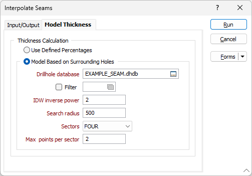
Use defined percentages
Select this option to calculate the thickness of the plies using the relative thickness percentages in the input Stratigraphy file.
Model Based on Surrounding Holes
Select this option to examine the intervals of surrounding holes to identify how Parent seams will be split into their Child components. Set the following data search parameters:
Drillhole Database
Double-click (F3) to select the Drillhole Database (DHDB) that contains the interval data you will use to model the ply thickness, based on the holes that surround the reference seam.
Filter
Select the check box and set a filter if you want to limit the information that is processed from the Drillhole database .
The following parameters define a data search ellipse that will be used to calculate an appropriate ply thickness:
IDW inverse power
The weighting given to each point that falls in the search ellipse is inversely proportional to its distance from the centre raised to the value entered in IDW Inverse power.
A fixed sized grid is created using IDW with a huge search radius that includes all input points. After that the rough IDW grid is used as an input into a minimum curvature spline.
Search radius
The Search shape, defined by the number of Sectors you enter (below), determines the Search radius value you need to specify:
- When the Search shape is CIRCLE, enter the radius of the data search circle in X axis units.
- When the Search shape is ELLIPSE, enter the radius of the search ellipse in the X and Y directions.
In general, a good starting point is to make the radius about 1.5 to 2 times the grid spacing.
Sectors
This number defines how many parts the search shape will be divided into for the data search. The maximum number of points is multiplied by the number of sectors to determine how many data points can be used within the overall search shape.
For example, if you choose FOUR sectors, the search shape is a circle, and the maximum number of points is 15, then the nearest 15 data points in each quadrant will be used, totalling 60 points.
Max points per sector
The maximum number of points to be used in the estimation of a block value. The maximum allowable value is 150. When more than one sector is defined, each sector can independently use up to the maximum number of points. (e.g. 150 pts x 4 sectors = 600 pts).
If more than the maximum number of points is found within a sector, the closest points are used.
Run
Finally, click Run to run the Interpolation process.