Multiple Thickness Grids
![]()
Seam File
Enter or double-click (F3) to select the name of the Seam Block Model file that will be used as an input to the gridding process.
The file format of a Seam Block Model file is the same as that of an Ore Block Model. In a Seam Block Model, the East and North dimensions of the blocks must be regular. However, the Z dimension of the blocks will vary, since they represent the thickness of the seams.
Thickness field
Double-click (F3) to select the name of the field in which the Thickness values are stored.
Material field
The Material field is a field containing both coal (seams or plies) and interburden (partings) and/or overburden codes.
X and Y fields
Double-click (F3) to select the name of the field in which the X and Y dimensions of the blocks are stored.

Multiple Grids
When you select this option, the function will generate individual thickness grids from the stratigraphic formations in the Seam Block Model file and write them to a Seam Block Model Control file.
Control file
Enter (or double-click (F3) to select) the name of the Control file.
Material field
The Material field is the field to which both coal (seams or plies) and interburden (partings) and/or overburden codes will be written.
Grid file field
The Grid file field is the field to which the name of each Thickness grid file is written.

Single Grid
When you select this option, the function will generate a single thickness grid from the stratigraphic formations and a material, in the Seam Block Model file.
Output grid file
Enter, or double-click (F3) to select, the name of the Grid file.
Material name
Enter a name. or click on the List icon to select a value from the Material field in the input Seam Block Model file.

Additional Points
Additional points, in a secondary file, may be used to improve the accuracy of the generated grid(s).
File
Double-click (or click on the Select icon) to select the name of the file containing additional points.
Elevation field
Double-click (or click on the List icon) to select the field in which elevation values are stored.
X, Y fields
Double-click to select the name of the fields containing the X, Y coordinates.

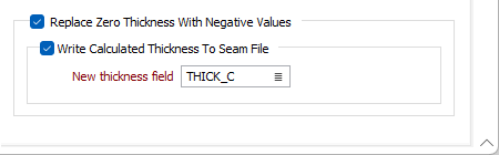
Replace Zero Thickness With Negative Values
Blocks that do not intersect a seam are given a zero thickness value. Select this option to model the thickness for any zero thickness records based on surrounding data (that has the same Material code).
For each seam with at least one point zero thickness, a grid is calculated using the non-zero thickness points. This intermediary grid is calculated using the IDW + Minimum Curvature method, and uses the same extents and polygonal restriction settings specified in the form.
For each point of zero thickness in that seam, the thickness of the intermediary grid at that X,Y location is calculated and the zero thickness is replaced with the inverse of that value.
The gridding process then proceeds as normal and the final grid is created with the updated seam thicknesses as the input points.
If an Additional Points file is selected, it is ignored for the creation of the intermediary grid.
If a seam has only one point of non zero thickness, the IDW + Minimum Curvature method is skipped and the inverse of that single thickness is applied to all the other points.
Write Calculated Thickness to Seam File
If this check box is selected, the inverse of the modelled thickness values (calculated at each zero location as described above) will be written to the nominated New Thickness field.
Enter, or click on the List icon to select, the name of the field to which the values will be written.