Ring Wireframe Report
![]()
To enable the tools on the Ring Design ribbon, ensure that a Ring Design layer is selected as the Active Layer. If nothing is selected in the display when you click on the Generate Wireframe button, the Selection Assistant will prompt you to select a ring or a drive.
Alternatively, you can Digitise the required object/s using the button in the Selection Assistant toolbar. The Selection Assistant will close, providing access to the tools used to create the object.
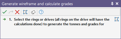
The Generate Wireframe and Grades form is then displayed.
Unless they are transparent, drive wireframes will obscure the drive strings underneath. To select a drive string before clicking the Generate Wireframes button, you will need to turn off the display of the drive wireframes.
On the Generate Wireframe tab of the form, set parameters to generate the wireframes that represent the area that will be blasted for either the current ring, the rings on a selected drive, or all of the rings in the design. If a ring is selected, the name of the current ring is displayed. If a drive is selected, "Multiple selected rings" will be displayed instead.
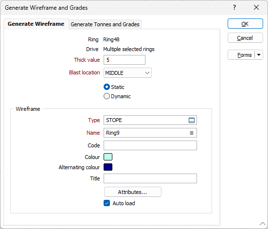
Thick value
The height and the width of the ring boundaries are used when generating wireframes of the area to be blasted. To estimate the depth of the blasted area, enter a Thick value which is an estimate of the extent of rock fragmentation at either side of the ring boundaries.
If a value of 4 metres is entered, for example, then we expect the rock to fragment 2 metres from either side of the ring boundaries.
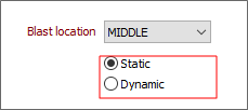
Blast location (Advance)
Select an option to control the positioning of the wireframe relative to the ring and choose whether the location is Static or Dynamic:
| Mode | Description |
|---|---|
| Static | Select this mode to generate planned blast wireframes with a fixed blast advance. |
| Note: This option will provide a single estimate of the blasted wireframe of a ring. Overbreak may be overestimated using this option. | |
| Dynamic | This option will generate wireframes aligned with a multi-ring blast. Using this option, estimated overbreak and underbreak are minimised. |
| This mode is the best option for curved drives. |
One of three blast location advance options - MIDDLE, FRONT, BACK can be selected:
-
MIDDLE - By default the wireframe is centred around the ring The advance occurs in both directions.
- FRONT - the wireframe is generated forward of the ring position - as if a free face exists on the opposite direction of the mine advance. The default mine advance will be the drive orientation.
- BACK - the wireframe is generated from the face of the ring in the opposite drive direction - as if the free face is located at the end of the drive and the mine advance is opposite to the drive direction.
Wireframe
Before you can generate wireframes and save them, you will need to specify their type and enter standard and (where appropriate) user-defined attributes for that type. Optionally enter a title for the wireframe that will be generated.
Colour and Alternating Colour
Specify a line colour for the wireframes. If generating multiple wireframes, specify an alternate colour that will be applied to every second wireframe. This will allow you to differentiate between adjacent stopes.
Attributes
To enter user-defined attributes, click the Attributes button.
Auto load
Select this option to load the generated output in Vizex. The default draw style for an auto-loaded wireframe is 3D Shaded.