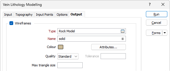
Output
On the Output tab of the form, specify the type and name of an Output wireframe.
Wireframe
Type and Name
Double-click or click on the Select icon to set the Type and Name of the wireframe that will be generated from the input strings.
Colour
Double-click the icon to set a colour for the Output wireframe.
Attributes
Click the Attributes button to set attributes for the wireframe output.
User-defined attributes may be mapped against the fields in the Input file. It is also possible to specify a default value for each attribute. Default values are used when a corresponding value in the Input file is either missing or is not mapped.
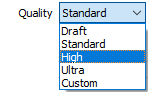
Quality
This setting provides a convenient way to control the quality and the speed of wireframe generation. There are five quality settings: Draft, Standard, High, Ultra and Custom.
Setting the quality to Draft allows the general shape of the output wireframes to be generated quickly.
With the exception of Custom, each quality setting has a pre-set error tolerance value. The error tolerance for Draft is approximately twice that for Standard, which, in turn, is twice that for High, etc.
Setting the Quality to Custom allows a user-specified error tolerance. There is no limit to the user-specified error tolerance value (and hence the minimum mesh size), other than that imposed by available system memory.
Tolerance
Specify a tolerance (in Grid units).
Max triangle Size
To eliminate large meshes, specify a Maximum Triangle Size parameter in grid units.
By default, mesh size is controlled by the tolerance parameter, which specifies the maximum error between the rendered surface and the actual surface. Typically, larger meshes are used where the surface is relatively flat, and smaller meshes are used where the surface has high curvature.
If a Max Triangle Size is specified then all triangles will be that size, or smaller if they fail the tolerance test.
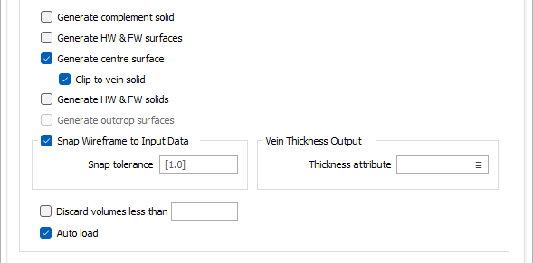
Generate complement solid
If this option is selected, then a separate solid wireframe will be generated which encloses the space between the contact surface and the edge of the ROI, one that is external to the INCLUDE intervals specified on the Input tab.
The complement solid wireframe will have the same name as the primary wireframe, appended by a suffix “_complement”.
Generate HW & FW surfaces
If this option is selected, two separate wireframe surfaces will be generated, one representing the top surface of the vein, and one representing the bottom surface of the vein.
These top and bottom vein surface wireframes will be given the same name as the primary solid vein, appended by the suffices “_surface_1” and “_surface_2” respectively.
Generate centre surface
Select the check box to output the vein centre surface. Centre surface generation for correlated veins uses the same implicit model function as Generate HW & FW surfaces by outputting the surface where f = zero.
For uncorrelated veins, a dedicated model for the centre surface is generated, since the HW and FW surfaces are defined by separate and unrelated implicit functions. Care needs to be taken to ensure that, should the HW and FW surfaces intersect one another (e.g. where there is pinching), the centre surface must intersect the HW and FW surfaces precisely at the same locations. This means that modelling of the centre surface must be done after the wireframes of the HW and FW surfaces have been generated and their precise intersections determined.
To identify the centre points of the vein, a ray is projected perpendicularly down from each triangle on the HW surface until they intersect the FW surface. If the normal of the intersected triangle on the FW is within 15 degrees of the projecting ray, then the mid-point of the ray is accepted as a point on the centre surface.
This means that modelling of the centre surface must be done after the wireframes of the HW and FW surfaces have been generated and their precise intersections determined.
To identify the centre points of the vein, a ray is projected perpendicularly down from each triangle on the HW surface until they intersect the FW surface. If the normal of the intersected triangle on the FW is within 15 degrees of the projecting ray, then the mid-point of the ray is accepted as a point on the centre surface.
Clip to Vein Solid
If the Generate centre surface option is selected, you can select Clip to Vein Solid to clip the surface to within the modelled vein.
Generate HW & FW solids
If this option is selected, two separate wireframe solids will be generated, one representing the top solid of the vein, and one representing the bottom solid of the vein.
These top and bottom vein solid wireframes will be given the same name as the primary solid vein, appended by the suffices “_solid_1” and “_solid_2” respectively.
Generate outcrop surface
If Topography generation has been configured, you can select the Generate outcrop surface/s option to create outcrop surfaces for the output.
An outcrop surface is the footprint of the wireframe solid where it intersects with topography. Surface outcrop wireframes are very useful when preparing features like maps. Attributes for the surface outcrop are inherited from the solid wireframes which prepends with “Outcrop_“.
Note: If there is no intersection between the topography and the solid, then no "Outcrop_" wireframe will be created, as it would be empty.
Snap wireframe to input data
The generated wireframes may be slightly offset from the points they were created from. Select this check box to snap the wireframes to the input data. Snapping will move the closest triangle to each snap point, if the distance between the two is less than the specified Snap tolerance.
If you do not enter a value, the default tolerance is 1 metre.
Snap points are the start and end points of the INCLUDE intervals.
If an INCLUDE interval starts at a collar, then it will only be added as a snap point if the Create intercepts at collar check box option is selected on the Input tab.
Similarly, if an INCLUDE interval ends at the end of a drillhole, then it will only be added as a snap point if the Create intercepts at end of hole check box option is selected on the Input tab.
Vein Thickness Output
To calculate and write the thickness of the vein to the vein wireframe and centre surface, specify the Thickness attribute for the model.
Vein thickness is computed for each vertex of the solid vein wireframe and written to the specified wireframe attribute.
Discard volumes less than
If this option is selected, all independent triangle shells with a volume less than the specified minimum volume will be removed.
Any value less than or equal to zero will disable volume removal.
Auto load
Select this option to load the generated output in Vizex. The default draw style for an auto-loaded wireframe is 3D Shaded.
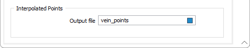
Interpolated Points
Enter (or click on the ellipsis button to select) the name of an Output file to which the interpolated points will be written.
This DAT file will contain the key data points used to define the vein model. These are typically the start and end coordinates of the INCLUDE intervals. Each data point will contain the fields “EAST”, “NORTH”, and “RL” which define its coordinates, and a “VALUE” field which defines its proximity to the top or bottom vein surface. Points residing on the top and bottom vein surfaces will be assigned a “VALUE” of 1 and -1 respectively.
While the model generation process is performed, progress messages will be shown to indicate to the user how many veins have been modelled so far - e.g. Modelling Vein XXX (1 of 5).