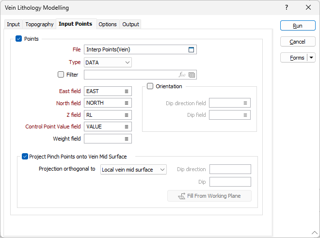
Input Points
Use the Inputs Points tab to specify a set of points that can be used to constrain the surface of the
Note: Zero-valued extra input points are treated as pinch points, independent of the When vein code is missing option on the "Options" tab. That is, if zero-valued extra input points are specified, and "Ignore" is selected for the When vein code is missing option, then the vein will pinch as the locations indicated by the extra input points, but not where drillholes do not contain any contact intervals.
Points
Select this check box to constrain the modelling process so that surface of the model is coincident with a set of input points.
File
Double click (or click on the Select icon) to select an Input file. Typically, the Type of the Input file will be a DAT file containing point sample data. Other file types are also supported; including Survey, Structure and Report. You can optionally apply a Filter to the records in the file.
Note: For the attributes on the tab, you can select an value using the list button or right-click and select Edit Expression to open the Expression Editor and use an expression. Note also the information in Output Field Name Attributes.
East, North and Z fields
Specify the names of the fields in which Easting, Northing, and Z coordinates are stored in the Input points file.
Orientation
The orientation of the generated wireframe is influenced by the Dip and Dip Direction of the points or strings in the Input file.
Use the inputs to include structural information (dip and dip direction) to points, and the surface will honour that orientation. Enter an orientation that is normal to the surface where it coincides with the input points.
Double-click (or click on the List icon) to select the name of the Dip Direction field (see Dip and Dip Direction). The available fall direction range is 0-360 degrees.
Double-click (or click on the List icon) to select the name of the Dip field (see Dip and Dip Direction). The available incidence angle range is 90-(-90) degrees.
Any dip direction or dip values outside of the specified ranges (i.e. negative dips) are ignored and a warning message is displayed after processing is complete.
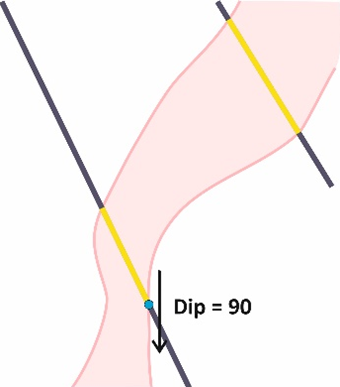
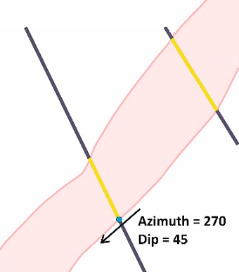
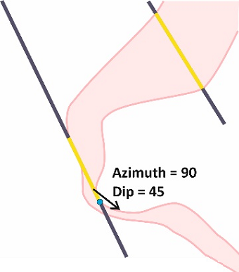
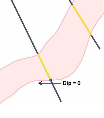
Examples of use, cross-sectional view:
|
Dip direction = 270, Dip =90 |
Dip direction = 270, Dip = 45 |
|
|
|
|
Dip Direction = 90, Dip = 45 |
Dip direction = 270, Dip =0 |
|
|
|
Control Point Value field
Select the field in the file where the control point value is stored. This value is optional when the Orientation option is selected, otherwise it is required.
If a field name is specified, the value contained in the field will determine the behaviour of the Vein model:
-
Positive values (+1) will modify the hanging wall surface of the Vein model.
-
Negative values (-1) modify the footwall surface of the Vein model.
-
Zero (0) values represent pinch points in the model, which forces the application to pinch the Vein at that point.
-
If the field value is left BLANK for individual records in the input DAT file, then those input points will not control the location of the Vein surfaces.
Weight field
Use the Weight field option to select the field in the input file which contains the Weight attribute, if required.
In some cases, custom data points may contain a Weight attribute which is useful where a guide which does not need not be honoured exactly is required by the modeller. This is especially useful where the Snap to data option is enabled and you do not want the resulting wireframe to snap to the custom data points.
With a Weight field selected, if the weight attribute for a custom data point has a value of less than 1, it will not be snapped onto.
Project Pinch Points onto Vein Mid Surface
Select this option to choose one of the following plane projection options:
| Option | Description |
|---|---|
| Local vein mid surface | Pinch points are projected orthogonally to the vein mid surface, according to its local curvature. This is the default option. |
| Plane of pinch points | The projection direction is orthogonal to the plane of best fit of the pinch points. At least 3 pinch points must be present. |
| Custom plane | The projection direction is orthogonal to a plane defined by a user-supplied Dip and Dip Direction. If a suitable display layer is open, these can be automatically filled from a working plane in Vizex by clicking the Fill from Working Plane button. |
| Plan View | Pinch points are projected vertically. |
| Looking North view | Pinch points are projected in the north-south direction. |
| Looking West view |
Pinch points are projected in the east-west direction. |