Wireframes
The inputs on this tab are enabled when you select the Wireframe input mode on the Files tab of the Unfolding form.
Fold bearing
When wireframes are used to interpret the folded strata, you must specify the direction of the fold. The input wireframes are cut perpendicular to this direction in order to build an unfolded model.
In effect, selecting the Wireframe input mode is equivalent to using Strings (which are the result of vertical cutting) but without the need for Link files (see Strings).
Footwall and Hanging-wall Surfaces
On the Wireframes tab of the Unfolding form, if you have chosen not to use a centre-line surface instead (see below) select the sub-surface and the surface (footwall and hanging-wall) structures that will be used to interpret the folded strata.
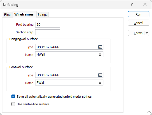
You can use the Wireframe Boolean function to generate the footwall and hanging-wall structures used as input to this process. It is important that the entire block model lies between these surfaces. Blocks that fall outside will not be unfolded.
In Wireframe input mode, string direction is taken into account. All input strings must have the same direction. Sections should be sorted so that the folded model can be properly built.
Save all automatically generated unfolded model strings
Select this option to write the generated strings to the Section Link and Link Between Sections files.
If the attempt to build a folded model fails (sometimes the strings produced as a result of cutting the wireframes are not sufficient) the resultant strings can be used in Strings input mode. An iterative process of string correction prior to input, may be used to unfold a problematic folded model.
Use centre-line surface
When this option is selected, you will be prompted to enter a single Centre-line surface, rather than two covering surfaces:
The function will generate diagonal bisecting lines from each centre-line point to determine an initial model thickness. This is then reduced to avoid bisecting line intersections.