Setup Polygons
![]()
If the ore and waste parcels are defined by polygons, click on the Polygons tab (or select the Setup (Polygons) option on the Grade Control tab, in the Grade Control group, when working interactively) to configure the Z extents settings which will be used to determine the thickness of each parcel. The function uses the thickness value to generate solid wireframes for the polygons. The reserve estimation is subsequently conducted on these wireframes.
Note: When processing tagged polygons, the Vizex viewpoint (at the time of pressing Report on the Grade Control tab, in the Grade Control group, is used to determine the Projection Plane from which polygons are extruded to produce wireframes. Therefore, the viewpoint should be aligned with the desired projection plane and direction before the tool is run.
![]()
Note: If selecting strings residing in different string files, the drop down lists allowing the selection of polygon fields in the string file only display fields common to all string files.
Spatial Definition
Position of projection plane
Specify how the position of the plane that is projected will be derived. In an open pit scenario this will typically relate to the Z values of the grade control polygons. In an underground scenario, this could relate to the position stope outline polygon(s). There are two options:
|
CONSTANT |
Select this option to use a specified constant thickness in the grade control calculation. |
|
FROM SELECTION |
Select this option to use the position of the selected polygons to determine the position of the projection plane(s). |
|
|
In an open pit scenario, select this option to use the Z values of the Polygon parcels that you will tag for use in the grade control calculation. |
|
In an underground scenario, select this option to use the position of the ring or stope outline polygon(s) as the plane which will be projected by the thickness. |
Polygon position
|
FRONT |
In an open pit scenario, if the position of the polygon represents FRONT, then the specified Z value corresponds to the Crest or top of the parcel. In an underground scenario, the polygon would represent the front of the stope. |
|
BACK |
In an open pit scenario, if the polygon position represents BACK, then the specified Z value corresponds to the Toe or bottom of the parcel. In an underground scenario, the polygon would represent the back of the stope. |
|
MIDDLE |
In an open pit scenario, if the polygon position represents represents MIDDLE, then the specified Z value corresponds to the mid midpoint of the parcel, for example, the middle of the bench. In an underground scenario, the polygon would represent the middle of the stope. |
Note: In an open pit scenario, you should be in Plan View when selecting polygons for tagging. In an underground scenario, you should align the view to the ring planes when selecting polygons for tagging.
Thickness
If you have selected CONSTANT to define the position of the projection plane, enter a Thickness value that will be used to generate solids and calculate volumes for the selected parcels.
Assign Average Density to Selection
This option can be used to assign the calculated average density back to the original polygons. Enable the check box and select the field that will be used to store the Density values for the polygons selected.
Note: For Imperial projects, Density and Void Density inputs are replaced with Tonnage Factor inputs and grade calculations will treat these values accordingly.
Include Polygon Attribute fields in Report
Use this grid to select attributes from the input polygon and write them to the Report file. This feature can be used to customise the report file, for example, for better categorisation of the records in the file.
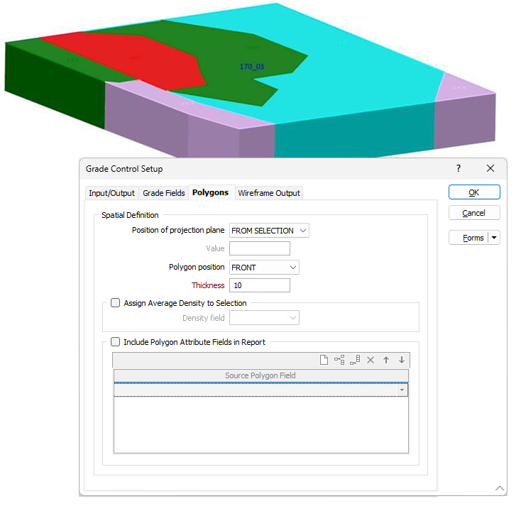
Open pit example:
Polygon(s) for the calculation should be selected for tagging in Plan View.
In this example the elevation or Z value of the tagged polygons is 170. The Position of Projection plane is set to FROM SELECTION and the Polygon Position is set to FRONT so the tool will use 170 as the Z value for the polygons which are at the crest of the bench.
Given the Thickness value of 10, the polygons will be projected down to the 160RL to derive the volumes that will be used in the estimation.
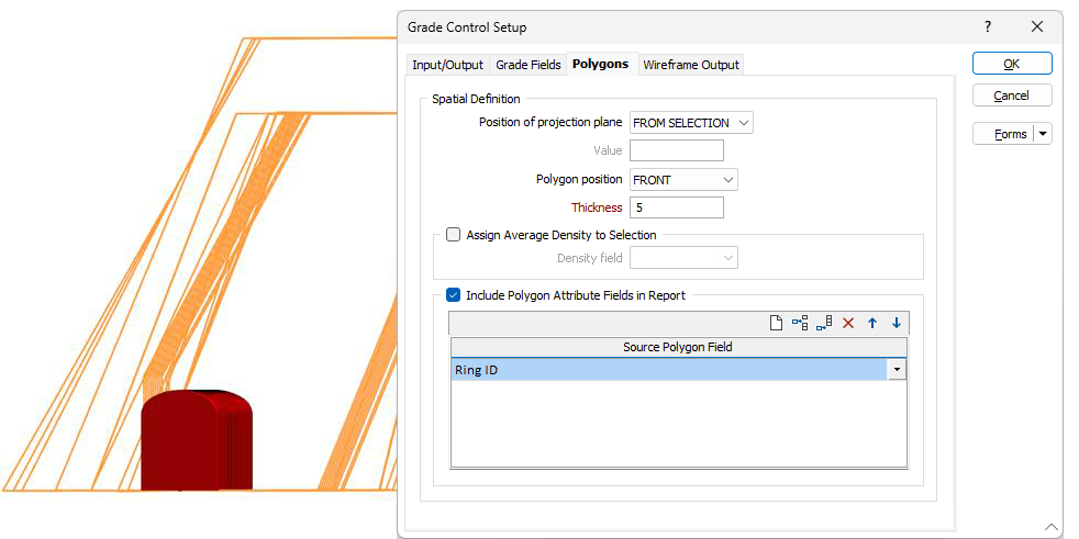
Underground example:
The view should be aligned to the plane of the polygon(s) before they are selected and tagged for the calculation.
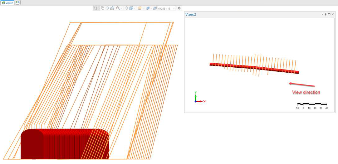
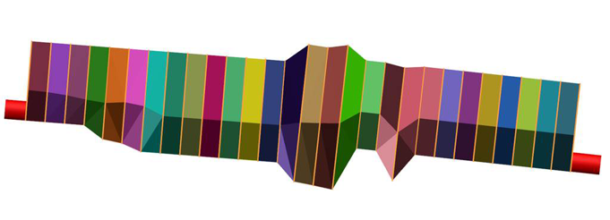
In this example, there are multiple polygons, each representing the ring plane for a stope. The Position of projection plane is set to FROM SELECTION and the Polygon position is set to FRONT. The tool will generate stope wireframes by treating each polygon as the front face and projecting away by the specified thickness in the view direction. The second image below demonstrates the output of this example. If the polygon position setting is set to MIDDLE, then polygons would represent the middle of a stope, so the tool would project by 2.5m in Towards and Away directions (either side of a polygon).