Create Dig Lines
![]()
Given a block model, an element’s cutoff grades for different material classifications, and minimum mining width parameters, an integrated mathematical programming solver is used to identify optimal dig lines.
Input
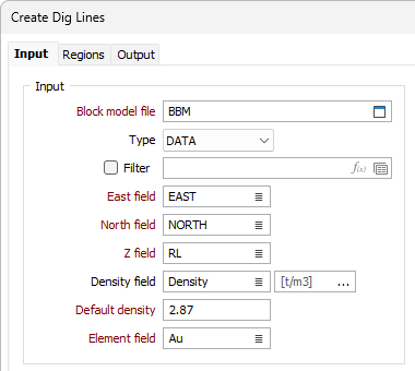
Block model file
Select the file containing the block model for which the optimum design is to be produced.
Easting, Northing and Z
Double-click to specify the names of the fields in which the Easting, Northing and Z coordinates are stored.
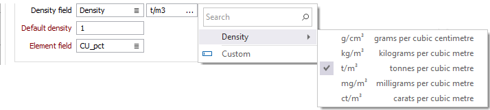
Density field
(Optionally) Double-click to select a Density field in the input file. If you specify a Density field, the function will calculate and enter the density of each continuous interval in the output file.
You can accept the default density Units [t\m3], select from the available units or select a Custom unit.
Default density
Enter a default Density value. The Default Density will be used when an Density value is missing in the record being processed. If there is no Density field in the input file, and you don't enter the default Density a value of 1.0 will be used in the calculations.
Element field
Select the field in the block model file from which the element grade for each block should be sourced.
Material Classifications
Define material categories and their cutoff ranges in ascending order. Use the buttons on the local toolbar to Manage the rows in the list.
Code
Enter a Code for each material category. The Code value will be assigned to a Material Classification attribute that is written to the output polygons/wireframes and report file. You can use this attribute to identify dig lines associated with different material, for example by applying colour sets.
From
Enter the lower bound for a material category. Values in this column are treated as inclusion bounds i.e. “>=” unless the value is 0. A value of 0 (which is the lowest value that can be specified in a From field) is treated as an exclusion bound i.e > 0. The Create waste dig lines check box should be used to generate dig lines from blocks with grades of 0.
To
The upper bound for a material category. The value is treated as upper limit i.e. “<”
The To column will auto-update as values are entered in the From field.
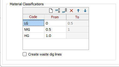
Create waste dig lines
Enable this check box to additionally produce dig lines from blocks with grades of 0, i.e. delineating waste regions.
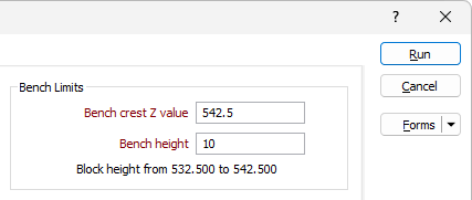
Bench limits
Bench crest Z value
Specify the Z value for the crest of the bench.
Bench height
Specify the bench height.
The tool will use these settings and the block model’s ‘parent’ block size to determine the Z extents of the run. The Z row in the Minimum Mining Width grid will auto-populate based on these settings, and the actual block extents used in the run will be reported.
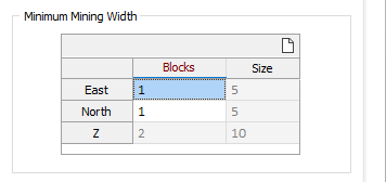
Minimum Mining Width
The mining width constraint is presented to the optimiser as a collection of blocks that form a template. The template floats over the block model cells to identify a collection of blocks that are of the same classification and fit within the template. Collections of blocks that meet this criteria form the output dig lines.
Use this grid to enter the number of ‘parent’ blocks that will be used to create the template.
Blocks
The number of ‘parent’ blocks used to create the template.
Size
Auto populated with the size of the mining width template in metres.
East
The (whole) number of ‘parent’ blocks in the X direction.
North
The (whole) number of ‘parent’ blocks in the Y direction.
Z
The number of ‘parent’ blocks in the Z direction. The settings defined in the Bench Limits group are used to auto populate this row.
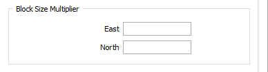
Block Size Multiplier
Specify Block Size Multipliers when you want to increase the size of 'parent' blocks by the values specified in the X or Y fields. These options may be useful if the input model’s X or Y ‘parent’ block dimensions are smaller than required. In this case block size multipliers could be used to effectively reduce the number of blocks being processed. Mass weighting is used when block size multipliers are used to combine blocks.
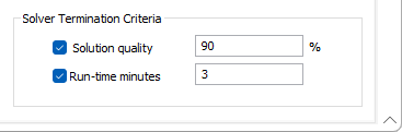
Solver Termination Criteria
Use these options to terminate the solver when one of the specified conditions is met. The conditions apply to each material category. For example, if you specify a run-time condition of 1 minute, the solver is given 1 minute to find a solution for each material classification.
When both conditions are used, the solver will terminate whenever the first condition is met.
Solution quality
Select this check box to terminate the solver when a specified solution quality is achieved.
Run-time minutes
Select this check box to terminate the solver after a specified number of minutes has elapsed.
Notes:
Block dimensions
More precise dig line delineations are likely to be produced when an input model with smaller ‘parent’ block dimensions is used. Larger ‘parent’ block dimensions would reduce the number of blocks that need to be processed, but may lead to less precise dig lines, particularly at the boundaries of a region.
The Regularise function on the Block Model tab, in the Reblock Model group, should be used prior to using this tool, if a model does not possess block geometry that complements the minimum mining width constraints and/or operational requirements, namely the bench limits.
![]()
For example, if you are mining to a bench height of 10 meters, but you have a block model with Z block dimensions of 1.5 meters, then you should consider regularising the model before using this tool. In that case, generating a model with Z block dimensions of 10 would be ideal.
Working with sub-blocked models
The tool always considers ‘parent’ blocks and the sub-blocks within each ‘parent’ block. This can have implications on the classification decisions it makes.
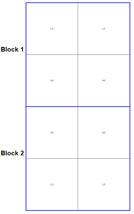
The image below shows a simplified example where there are 2 parents blocks: Block 1 and Block 2. Each ‘parent’ block has 4 sub-blocks. There are 3 material classifications: Low (LG), Medium (MG) and High (HG) grade. The minimum mining width is set to be equivalent to the size of 1 ‘parent’ block.
When processing these blocks, and given the minimum mining width constraint, the tool will consider each ‘parent’ block in isolation. The grade of its sub-blocks will be combined to determine the final grade. Therefore, the sub-blocks from Block 1, when combined, will result in the area being categorised as MG, and assigned to an MG dig line.
The tool will not combine the 2 HG sub-blocks from Block 1, with the 2 HG sub-blocks from Block 2, to generate a HG dig block.
This effect may lead to a discrepancy when visually comparing output dig lines that are generated from a sub-blocked input model. To prevent such cases, the Regularise function on the Block Model tab, in the Reblock Model group, can be used to prepare a regularised model.
This will ensure that blocks assigned to different material classifications will be based on grade values after mixing.