New Plane from Points
![]()
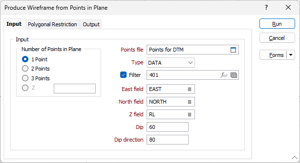
Input
Number of points in plane
Specify the number of points in the plane, as defined by the Points file. If only 1 point is available to define the centre and rotation of the plane, you must specify a dip and dip direction. For 2 points, specify a dip. Select 3 points to define centre of rotation, dip and dip direction from the Points file. If defining a horizontal surface at that Z, select the Z option and enter the Z value.
Points file
Select the file type and double-click to select the file containing the points you want to use in the process. If required, define a filter to selectively control the records to be processed.
East and North and Z fields
Specify the names of the fields in which Easting, Northing, and Z coordinates are stored in the Points file.
Dip and Dip Direction
If you selected 1 point, define the dip and dip direction for one point, modelling the DTM top Z and then the base Z. If you selected 2 points, define the dip. If you selected 3 points, the centre of rotation, dip and dip direction are defined in the Points file.
Output
Type and Name
Enter (or double-click (F3) to select) the Type (DTM) and Name of the wireframe that will be generated.
Code
Enter a character code that can be used to differentiate between this and other wireframes. For example, you might enter a rock type code and then use it later as a filter when reporting volumes, reserves, etc.
Colour
Double click (F3) to select the colour that will be used to display the generated wireframe.
Title
Enter a meaningful title for the wireframe you are creating.
Autoload
Select this option to load the generated output in Vizex. The default draw style for an auto-loaded wireframe is 3D Shaded.
Forms
Click the Forms button to select and open a saved form set, or if a form set has been loaded, save the current form set.
Run
Finally, click Run to run the function.